
Panels 15 and 16
With the delays in construction of the main CM structure, I wanted to show at least a little completed progress, especially in time to meet Fred Haise on June 22nd. I had already sent STL files for the wedge-shaped toggle switch extensions and the toggle guards to Marc Tessier of S&T Geotronics ( www.stgeotronics.com ) to 3D print, along with some cut and etch files to create some acrylic overlay panels, so I figured the best thing to do was to complete Panels 15 and 16. These were two small panels just to the right and left of the main control panel. Notably, these had the switches to turn on the COAS crosshairs (Crewman Optical Alignment Sight) used to dock the CM with the LEM.
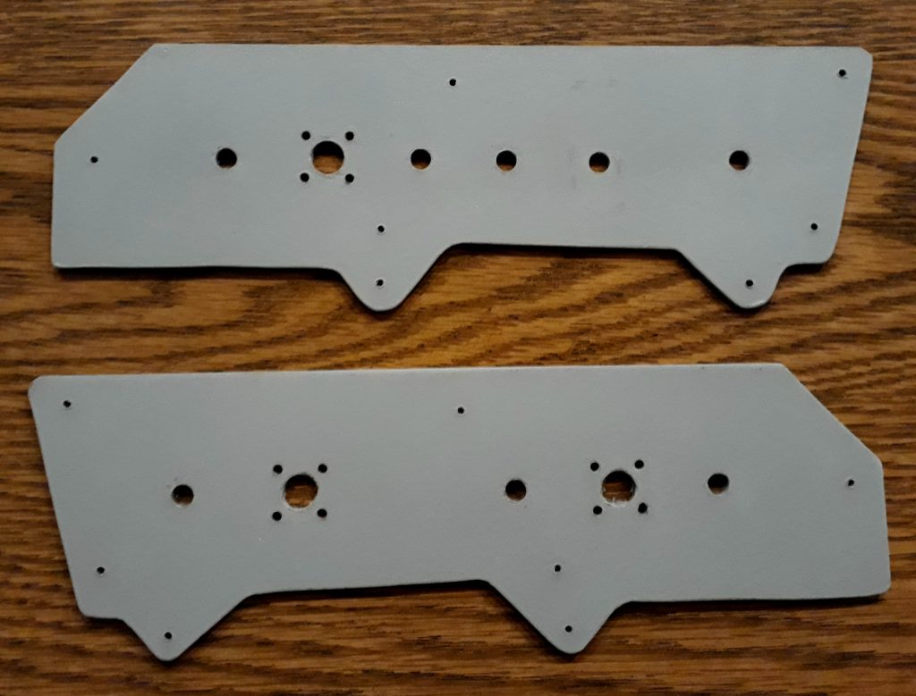
I made a copy of the panels from the NASA Command Module Displays and Controls manual, scaled them to actual size, and printed them to use as cutting templates. I transferred the templates to some hardboard, drilled holes for the switches and other items (drilling before cutting is easier), then cut them out with a jigsaw. I cleaned up the edges, them painted them in primer gray.
(Photo: Apollo Education Experience Project)
When we arrived in Columbus, Georgia for the Fred Haise presentation, we met up with Marc Tessier, who had been busy printing up some of the 3D items I had sent STL files for. These looked tremendous!
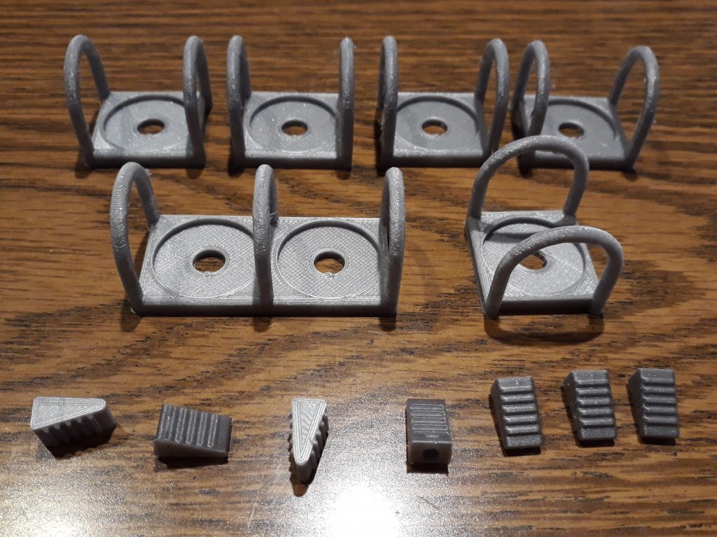
(Photo: Apollo Education Experience Project)
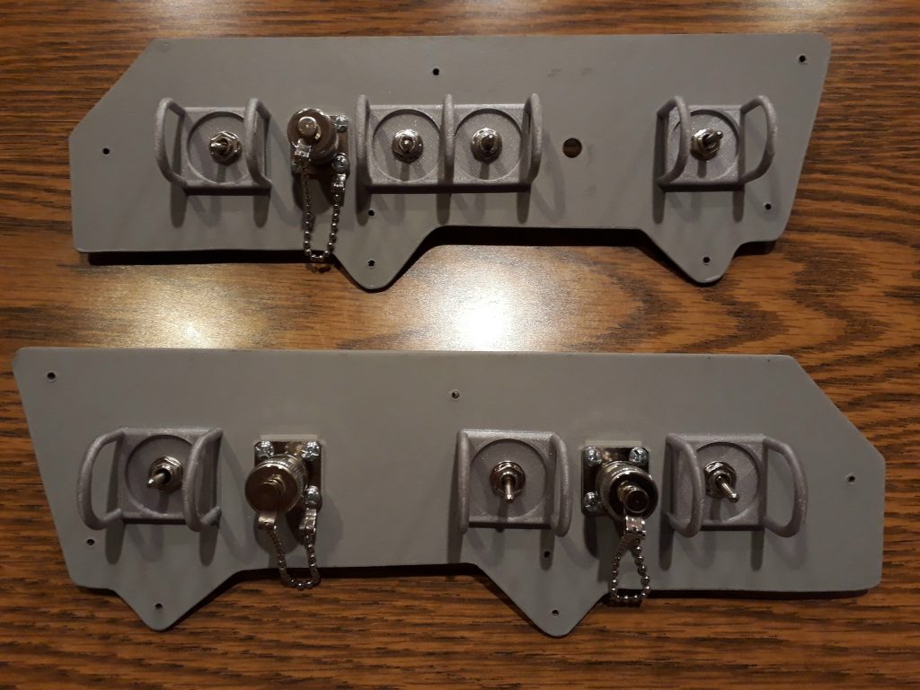
For several reasons, I chose to go with miniature toggle switches rather than full-size switches. I had been ordering a number of different types (2-position, 3-position, latching, momentary, etc.) so that I could install the correct switch in every location. I checked the manual, and installed the correct switches for these two panels. I also installed some panel-mount coax connectors with dust caps to serve as the auxiliary power connectors.
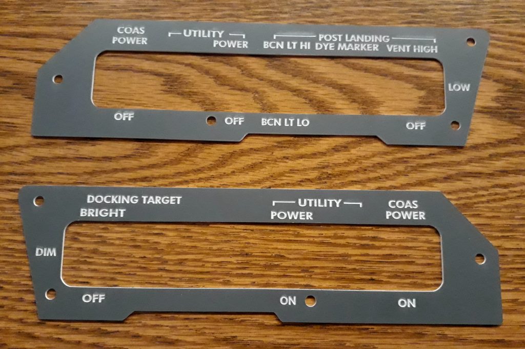
The panels cut and etched by Marc also looked tremendous:
(Photo: Apollo Education Experience Project)
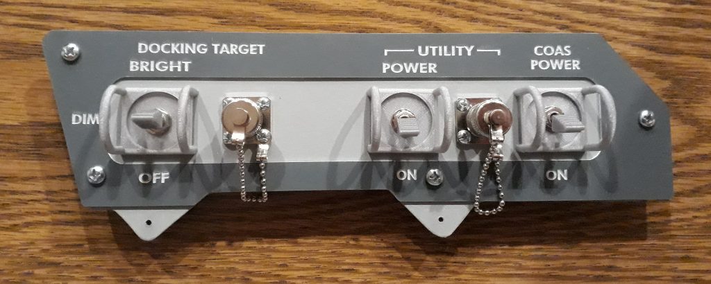
I mounted the overlays onto the panels using some wood screws. I had to drill an extra hole in one panel because I had accidentally omitted it from the cut file, but the acrylic drills easily and cleanly. I also mounted one final switch at this time – the covered toggle for the dye marker release. Part of it needed to fit under the overlay while part needed to go over it, so I had to wait until the overlay was on to install it. I had previously pained the cover with the same gray as the panel. Finally, I installed wedge extensions on the toggle switches. The finished panels looked amazingly real.
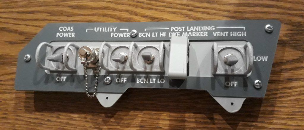
(Photo: Apollo Education Experience Project)
(Photo: Apollo Education Experience Project)
Being the total nerd that I am, I carried the completed Panel 16 with me to the Coca-Cola Space Science Center the next day. So when I got my photo with Fred Haise, I had this panel in my hand. Why this panel? Panel 16 was on the right-hand side of the main control panel, and would be the one on the same side as the Lunar Module Pilot (LMP). Since Fred Haise was the LMP for Apollo 13, it only seemed appropriate.
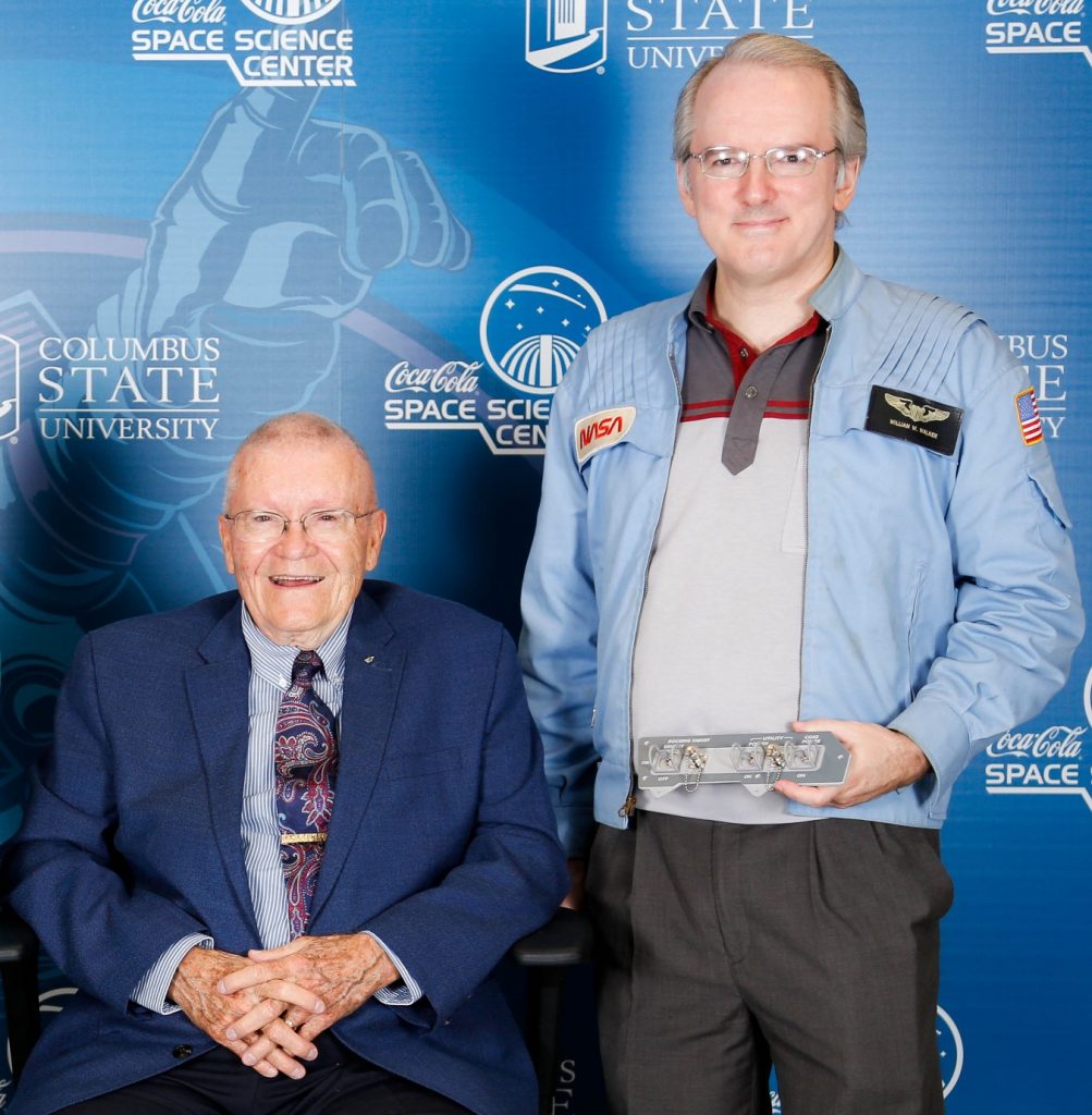
In my hand is the completed replica of Panel 16.
(Photo: Apollo Education Experience Project)


