
Dimmers
One of the goals of the project is to have working lights around the crew cabin, and hopefully working dimming circuits for them as well. There are three types of dimmers in the Command Module: those for the floodlights, those for the numerics (digital displays), and those for “integral” lights (the electroluminescent backlighting for the control panels). I need to create circuits for all three if I wanted them to work.
I had planned early on for dimmers for the floodlights. Even though the floodlighting would be build from LED lights, I figured the dimmers would still need to control a fair amount of power. I bought three 10-amp dimmers for the job. At 12 volts, each could control up to 120 watts, which would be more than enough for the floods. One problem, though – the potentiometers were soldered directly to the circuit boards. I would need to mount the potentiometers in the panels separately, plus provide on/off capability, so I bought some matching-value potentiometers with built-in switches. I de-soldered the potentiometer from the board (along with the on-off jumper), and soldered a length of multi-conductor cable in place. I soldered the other end of the cable to the tabs of the new potentiometer and its switch tabs.
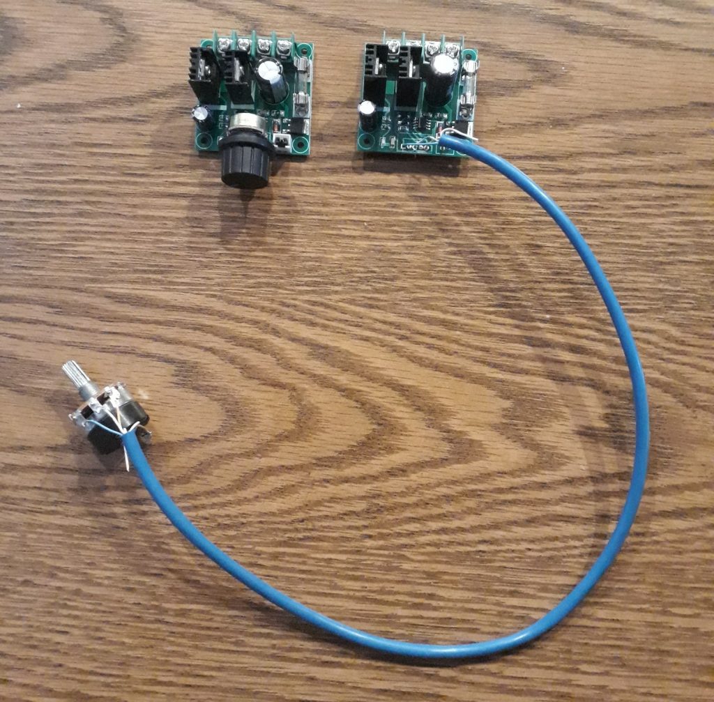
(Photo: The Apollo Education Experience Project)
There are only two things in the CM that have numeric displays, and I have dimming circuitry already built in to them. However, after adding up the number of gauges that will have backlights, I realized I needed to use more than just a bare potentiometer to dim them, since they would overpower it. I designed a simple circuit using a TIP-30A power transistor controlled by a 2N3906 transistor, which is in turn controlled by a potentiometer. I tested it with a pair of amber LEDs of the type used for the backlighting, and it worked great. I used this same breadboarded test circuit to test the completed backlight for Panel 101.
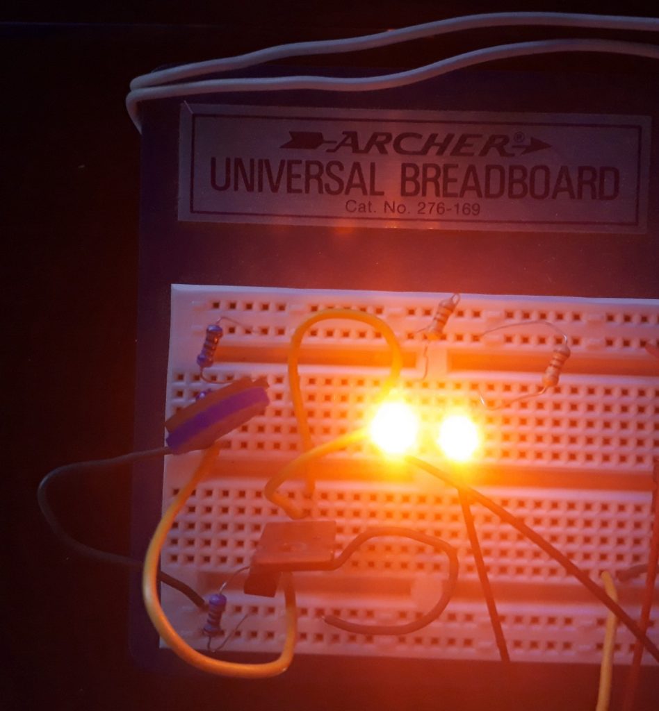
(Photo: The Apollo Education Experience Project)
I would eventually need three of these “integral” dimmers, so I dug up some old Radio Shack protoboards I had sitting around. I installed pairs of screws on the sides for power in on the left and dimming power out on the right. I connected the potentiometer to the circuit board with a multi-conductor cable similar to the one above, only without an on-off switch.
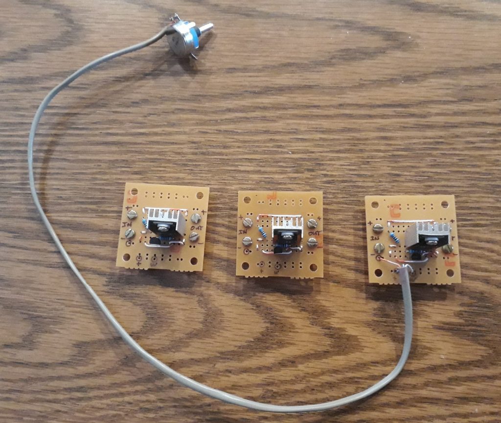
(Photo: The Apollo Education Experience Project)


