
Entry Monitor System (EMS)
Aside from the AGC (Apollo Guidance Computer), one of the key pieces of equipment in the Apollo Command Module was the Entry Monitor System, or EMS. This device had a few specialized functions, but arguably the most important was to monitor the speed and position of the CM during reentry into the Earth’s atmosphere. It provided information through three different displays:
– a digital readout of speed in feet per second or range in nautical miles,
– a special gauge that indicated the CM’s orientation, and
– a scrolling mylar graph with a scribe showing the CM’s deceleration in
Gs and various other graphic data.
It also provided for control of the Service Propulsion System (SPS) main engine for changes in velocity (a.k.a. “delta-V”).
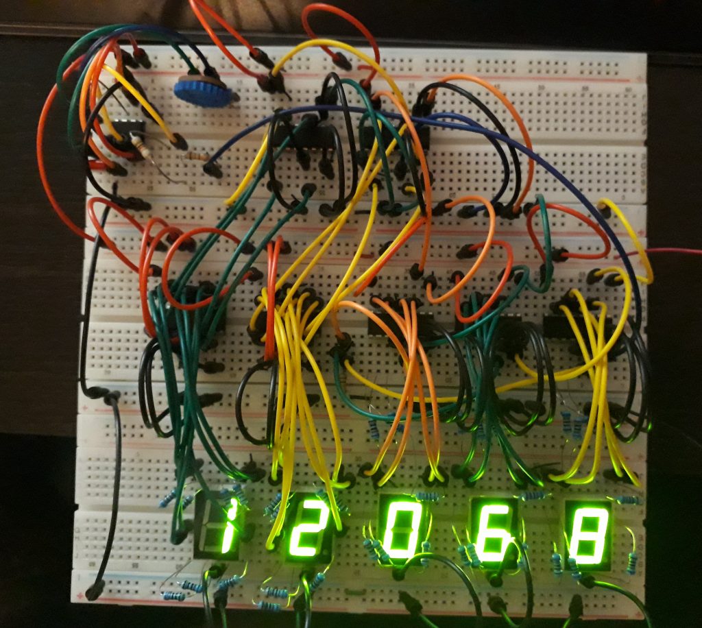
I knew I needed to model the EMS for the CM replica, but I also knew I could not simulate all of the functionality accurately with my level of expertise and the time available. So I initially planned to have just a simple countdown timer which would simulate the speed in feet per second, and which could be set with a couple of pre-defined values to simulate either reentry or a delta-V burn. The display on the EMS could register values up to 37000 for the starting reentry speed and up to 14000 for a delta-V burn, so I chose these.
Unlike the mission timer, I needed ICs that could count down as well as up, so I started with CD40110 chips. After breadboarding an initial counter, I learned that the CD40110 could not be set to a given start value, so I switched to the CD4510 for the first two digits (I didn’t need to preset the other digits since they start at zero). However, the CD4510 doesn’t have a built-in 7-segment driver, so I had to add two CD4511 ICs for the display. I then learned something interesting – the CD4511 ICs make the 6 and 9 differently from the CD40110. Since only the second digit was affected, I swapped out its CD4511 with a CD4543. Now all the digits matched.
I used a 555 timer to generate the clock pulses. I experimented with a number of different values to try to get realistic countdown speeds until I got something I was happy with. I built a small diode matrix so that various input lines could eventually be controlled from a switch and not have cross-talk. Until I add a switch, I manually controlled the functions with a jumper to V+. A few tests, and I had a working countdown circuit!
(Photo: Apollo Education Experience Project)
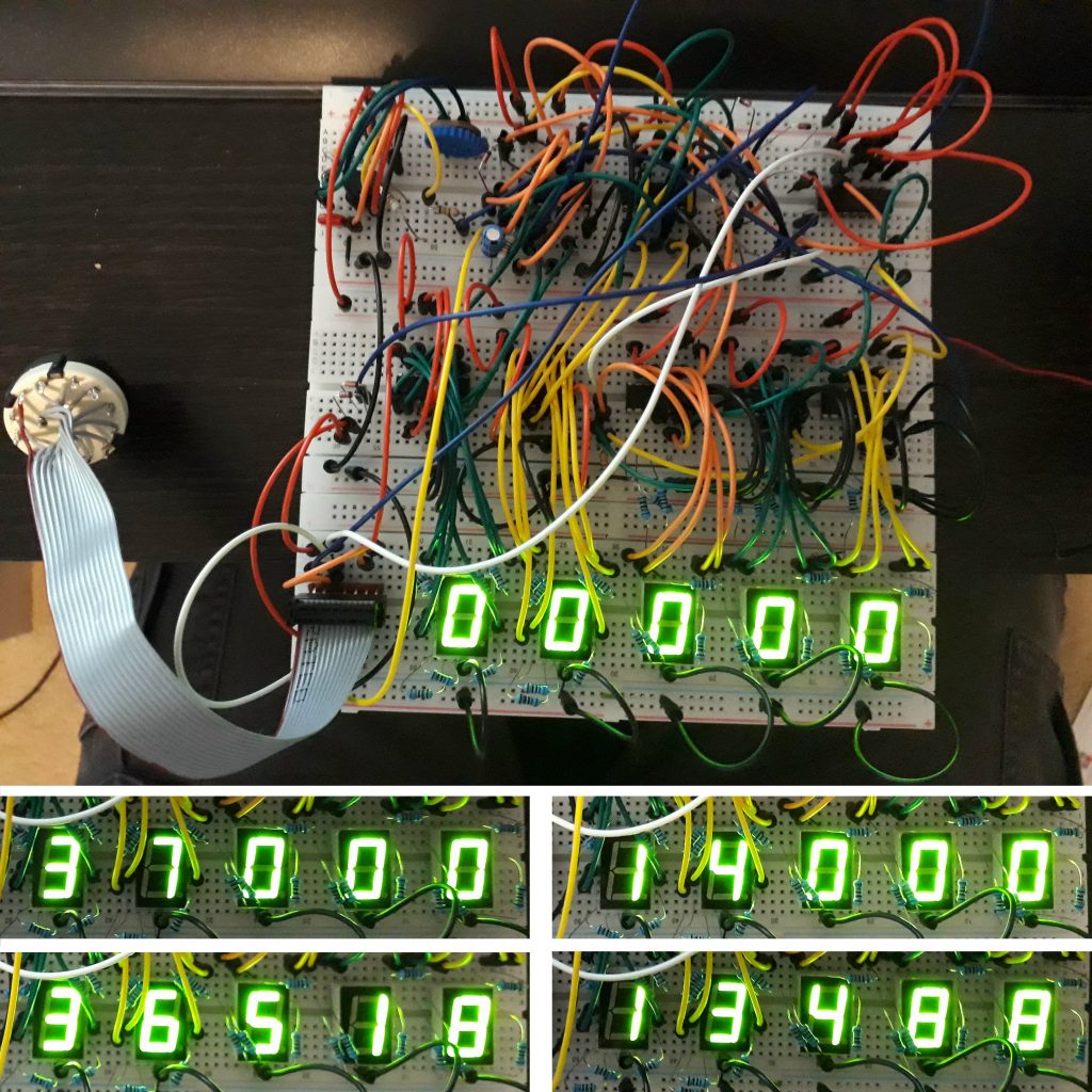
I did need a way to get it to stop at 0; otherwise the count rolled over to 99999! I added a CD4013 flip-flop (a dual circuit, but I only needed one) that would detect when the count reached 00000 and disable the counter. Since I now had an unused flip-flop, I used it to turn on the 0.05 G light when in entry mode or the SPS Thrust light when in delta-V mode, and turn them off when the count reached 00000.
The EMS had a rotary switch to select between modes, so I would use a rotary switch to set the values and start the countdowns. Based on a diagram of the EMS front panel, I assigned position 8 to set the reentry value of 37000, position 9 to start the reentry countdown, position 10 as a reset, position 11 to set the delta-V value of 14000, and position 12 to start the delta-V countdown. I connected these positions to the appropriate points in the diode matrix and tested. It worked!
(Photo: Apollo Education Experience Project)


