
Main Display and Control Panel (MDC)
I don’t think anyone will argue with the statement that the Main Display and Control Panel (MDC) is the single most iconic piece of the Apollo Command Module. I mean, with literally hundreds of switches, buttons, gauges, dials, indicators, and lights, nothing really illustrated with such emphasis the complexity of the task of building and flying a spacecraft to the Moon using the technology of the 1960’s. Even today, images of the MDC can be found on items such as mouse pads, coffee mugs, ties, and even shower curtains! It would not be an understatement to say that building a full-size MDC is a daunting task!
But as with any task, it has to start somewhere. In my case, it starts with 1/8″ tempered hardboard. Because I’m using miniature switches, they generally will not mount in anything thicker. The panel will eventually have a second layer of 1/4″ MDF on top of the hardboard to give it the relief necessary, but that will come later. For now, I started by transferring a full-size drawing of Panel 2 (the center panel) to a sheet of 1/8″ hardboard, including marking the locations of all switches, screws, and other openings.
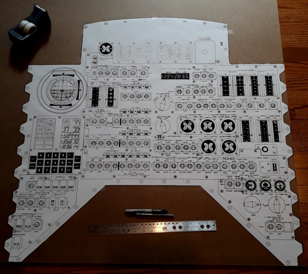
(Photo: The Apollo Education Experience Project)
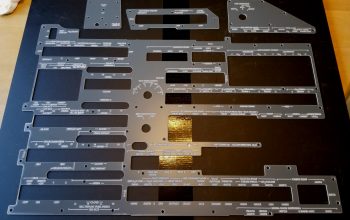
Next came the tedious process of drilling the holes and cutting out the openings. All the toggle switches required 1/4″ holes, but the rotary switches took slightly larger ones and the screw holes took smaller ones. #8 screws would be used to mount the panel itself, but #6 screws would be used to mount various components into the panel. Openings for the round gauges were cut using circle saw bits. After all of that drilling was done, I drilled pilot holes for the remaining openings, then cut them out using a fine jigsaw. Squaring up the holes for the talkbacks was definitely a challenge, as was cutting openings near the edge without fracturing the hardboard. But slow and careful work did the job.
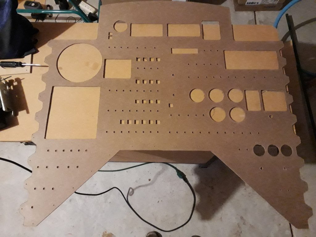
(Photo: The Apollo Education Experience Project)
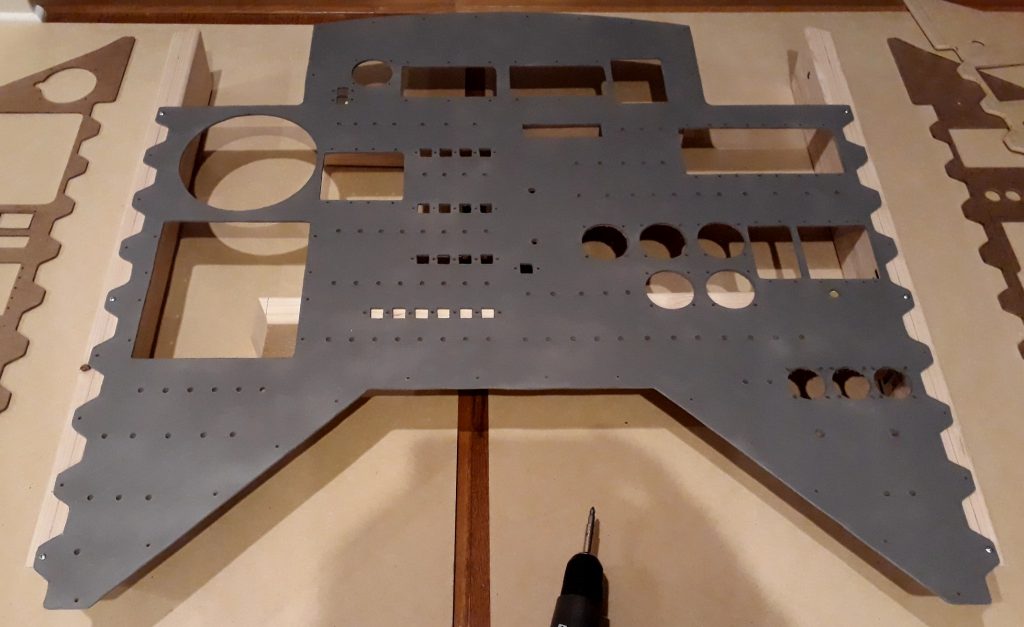
Even though the hardboard would be the back layer of the completed panel, enough of it would show that would require it to be painted. After looking at a number of colors, I selected a shade of gray called “Granite” that had both paint and primer in the same can. While it is likely not very close to the actual color used in the original CM, it looks pretty good.
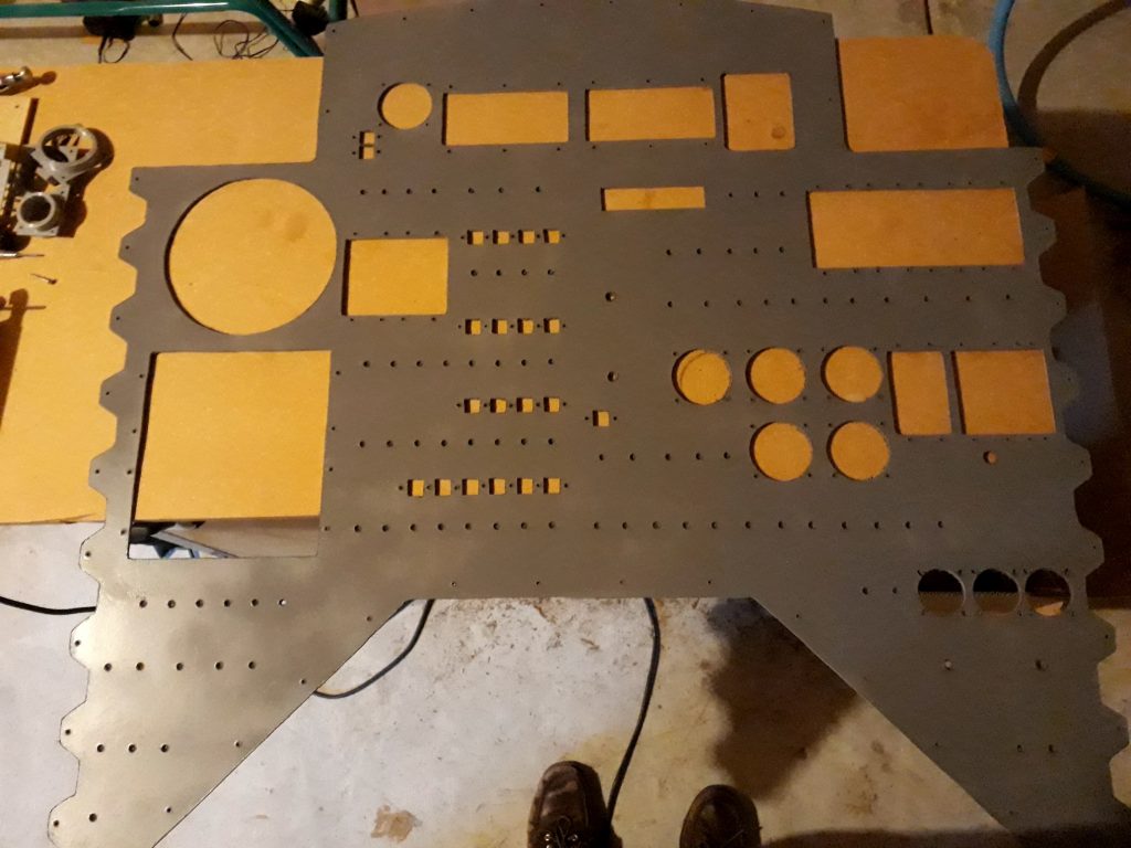
(Photo: The Apollo Education Experience Project)
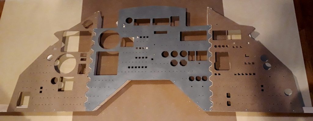
Once the hardboard for Panel 2 was complete, I repeated the process for Panels 1 and 3. Even though I had painted Panel 2’s hardboard, I chose to wait on painting 1 and 3. This was because I realized I was going to need these to serve as templates for building the MDC’s support structure. If I painted them now, I may have to repaint them later. But now that I had something tangible for all three of the MDC’s panels, I had to see how it looked so far, so I fit them together for a “family portrait”. Even unpainted and with nothing mounted, it is a thing of beauty.
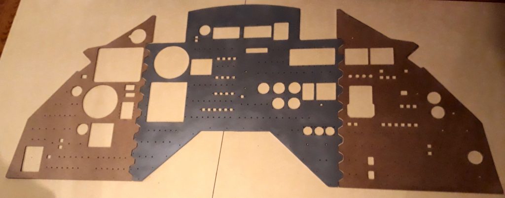
(Photo: The Apollo Education Experience Project)
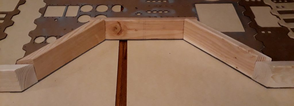
Next, I needed to build the support structure for the MDC, which will mount in the framework of the CM. The computer model showed that the most complicated piece of this would be at the foot of Panel 2. The large “notch” at the bottom of Panel 2 is to make room for the docking tunnel, which allows access to the LM when the two craft are docked. Also, the MDC is not mounted flat, but is at a slight angle. These items made for some difficult geometry in the form of multiple compound angles for cutting the 2x4s. But after some careful measurements (and yes, some trial and error), the frame of Panel 2’s base was complete.
(Photo: The Apollo Education Experience Project)
Now that the hardest part of the framework was done, I cut some more 2x4s for the supports between the panels. The DSKY, gauges, and other items come extremely close to the edges of the panels, so there is precious little tolerance in the spacing, which is just barely over the 1-1/2″ thickness of the 2x4s. I measured the center of the edges, then measured off the locations of a few key screw holes for mounting Panel 2.
(Photo: The Apollo Education Experience Project)
I continued by attaching these two pieces to the support structure previously build for the base of the panel. I then positioned the hardboard for Panels 1 and 3, then attached them with a few key screws as well. Now I had a structure ready to mount in the CM for the MDC.
(Photo: The Apollo Education Experience Project)


Hi mate Colin from downunder in New Zealand. Was wondering if you could steer me in the right direction as to images to copy for the many gauges on the instrument panel. Many thanks
If you mean the drawings of the various CM panels like Panel 2 in the first photo, they are available by searching for “Command Module Control Panel” on the Internet.
But if you mean the items I used to create the replica gauges themselves, I created all of those individually with a graphics program and printed them on a combination of paper and transparencies so I could create a layered effect.