Electrical Service
The CM will require power to light its lights and run all of its various electronics. The plan is to have the service entry connect where the Service Module (SM) umbilical would attach, which is just to the right of center when looking from the Lower Equipment Bay (LEB). This is why I placed the support for the electrical box there.
The CM won’t need a lot of power, but I plan on having some redundancy (as well as providing a “Main Bus A” and “Main Bus B”). To this end, I chose an electrical box that would support two legs of power. I also chose two dual 15-amp breakers to provide a total of four circuits. Two of those circuits would provide the power for Main Bus A and Main Bus B, while the others are for expansion. I have a specific purpose in mind for one of them, but that will be a surprise for later.
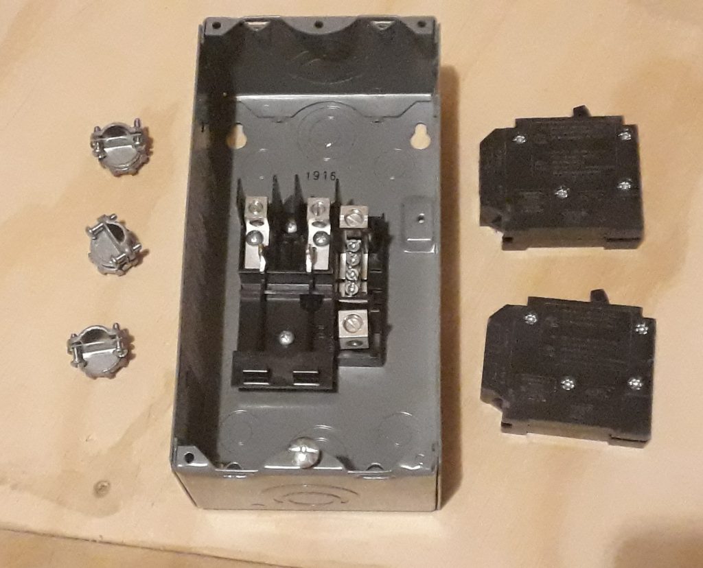
(Photo: The Apollo Education Experience Project)
Before mounting the electrical box, I marked where the access door would go. There really is a small door at this point in the CM, but it is for a different purpose – I’m just re-tasking it. I also knocked out several entry openings and installed cable clamps. I mounted the box on the support I installed so that the breakers would line up with the access door. I had thought that the mount points of the box would fit onto a 2″x4″, but it turns out they’re too far apart. What I did was knock out the smallest of the rear-entry openings and use them as attach points.
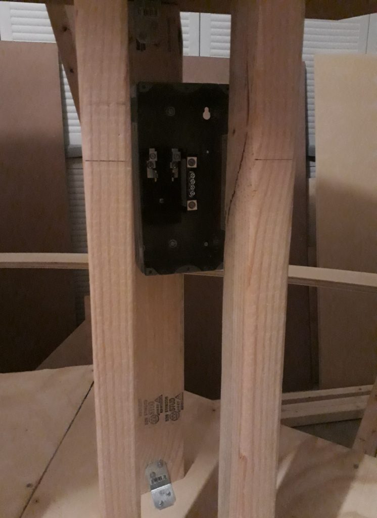
(Photo: The Apollo Education Experience Project)
I installed the two dual-circuit breakers in the box. Then, I inserted some 12/2 grounded wire for the service entry – one for each leg – through one of the cable clams and tightened it down. I connected one hot lead to each breaker and the neutrals to the neutral bar. I discovered at this point that the box did not come with a ground bar, so I’ll need to install that later.
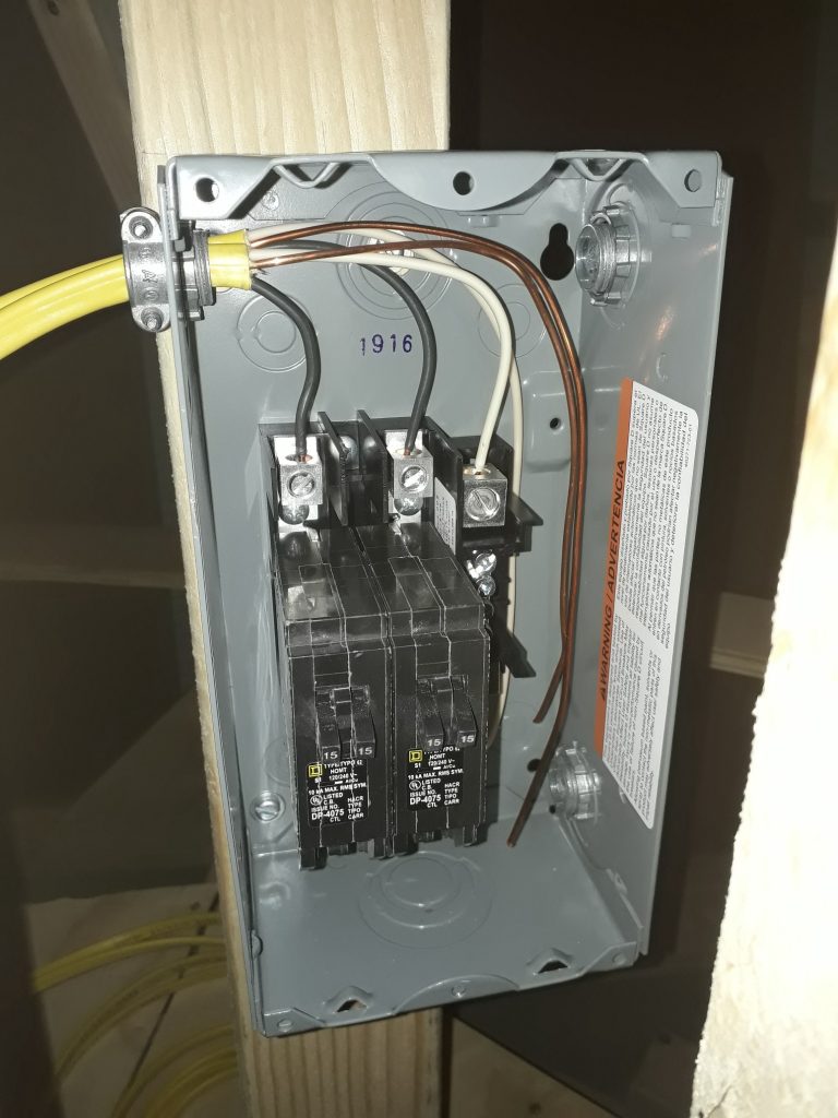
(Photo: The Apollo Education Experience Project)
Finally, I closed up the box and verified that the breakers were aligned with the proposed access door and would be easily accessible.
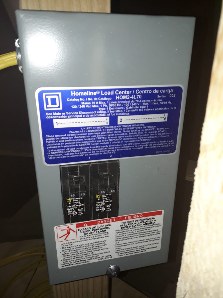
(Photo: The Apollo Education Experience Project)

