
Gauges – Part 2
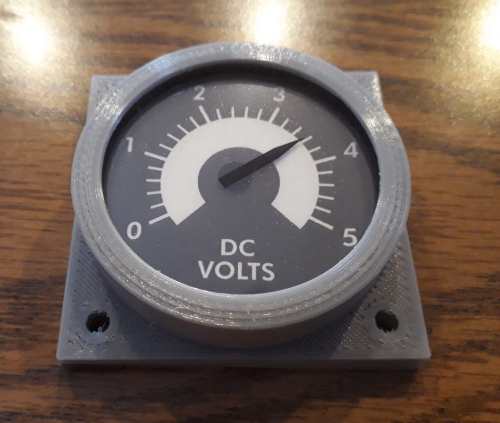
I’m beginning to work on Panel 101, which will be one of the first completed control panels to be installed in the CM. Although the switches will be non-functional, the one gauge will be backlit. Using the same patterns for the round gauges described in an earlier article, I 3D-printed another set. I printed a needle on one transparency and a hub on a second transparency, and printed a scale on some plain paper. I cut these out and sandwiched them between some acrylic circles to create the gauge.
(Photo: The Apollo Education Experience Project)
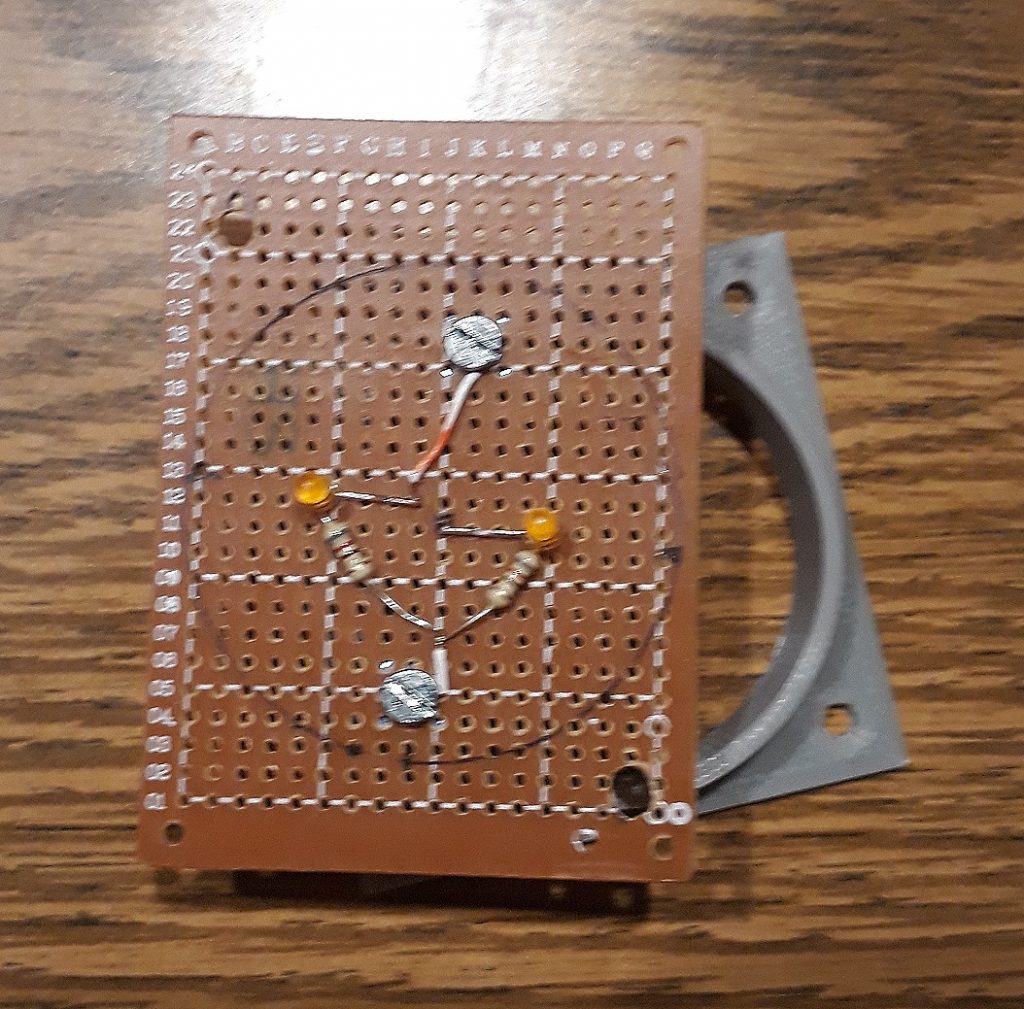
To make the backlight, I soldered two amber LEDs and their current-limiting resistors in parallel onto a small protoboard. I installed a pair of screws to act as terminals for attaching power, then soldered some leads between them and the LED circuit. I drilled a pair of mounting holes, and the circuit was complete. Similar backlighting would be needed for all of the other gauges, so I made sure to keep this simple since I would be making more of them.
(Photo: The Apollo Education Experience Project)
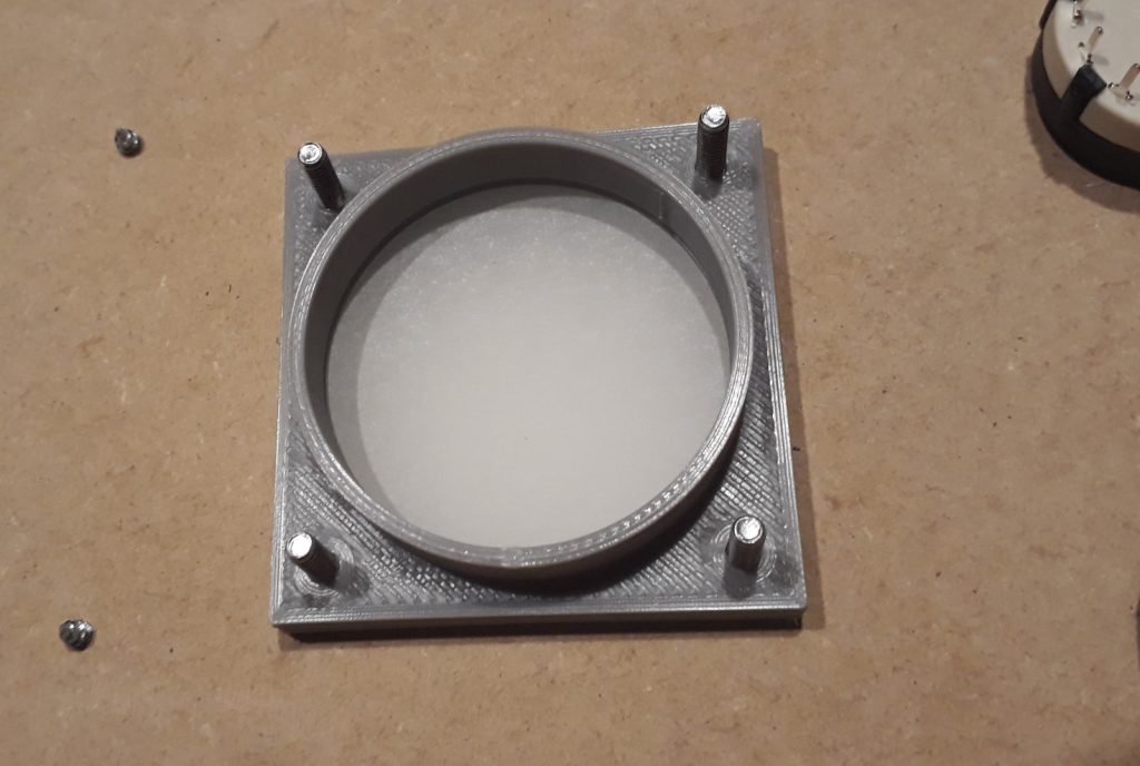
I installed the gauge into the panel and aligned it in place with two screws. To provide additional depth for the LEDs, I added a second insert flipped so that its plate matched up with the other insert. I added a piece of tracing paper sandwiched between the two plates to serve as a diffuser for the light.
(Photo: The Apollo Education Experience Project)
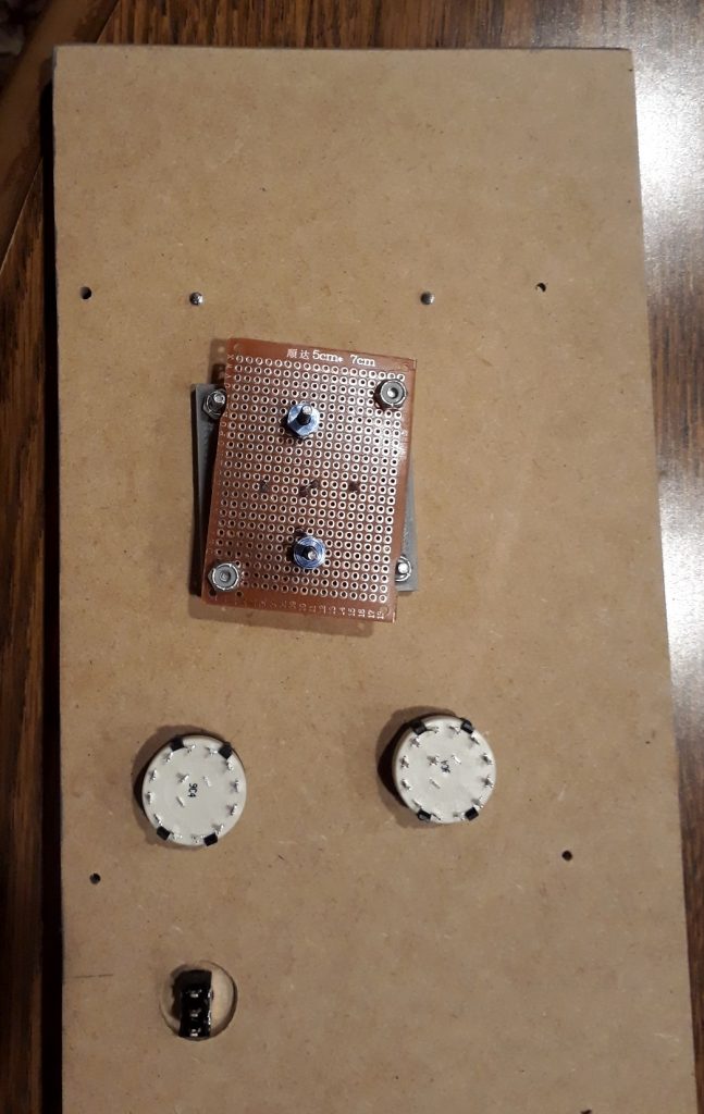
I fastened two of the screws with nuts, then started to install the backlight circuit. I slightly miscalculated the distance between the screws, and found that I needed to cut a little of the circuit board away to make room for the first two screws. Once this was done, the circuit mounted easily, and I secured it in place with some nylon locknuts. Yes, I know the circuit board is at a funny angle. It’s necessary so that the mounting holes won’t be right on the edge of the board. I probably should have bought the next larger size of protoboards, but these will still work fine like this. Nobody will see them on the completed CM anyway.
(Photo: The Apollo Education Experience Project)
Before actually installing the panel in the CM, I wanted to test and see how the backlighting looked. I had breadboarded a dimmer circuit (see the article on the dimmers), so I connected the backlight board to it and applied power. The lighted gauge looked very authentic!
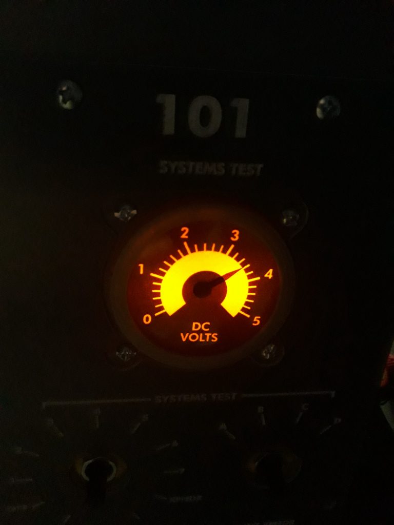
(Photo: The Apollo Education Experience Project)


