
FDAI (or “8-Ball”) – Part 4
Now that some of the electronic components I ordered have come in, I can get the lighting on the FDAI done. Looking at a real FDAI, there are two parts to the lighting — the rate scales and the ball itself.
To light the rate scales, I decided to insert LEDs in cutouts on the edges of the middle sheet of plastic centered with the three scales. The LEDs I ordered are 3mm, natural-white LEDs complete with 20cm wire leads and built-in resistors for 12-volt operation (convenient, since the Command Module DC power supply will be 12 volt). Unfortunately, the middle sheet of plastic is only 2mm thick.
To make the LEDs fit, I took my Dremel tool (a Craftsman clone, actually), along with a fine grinding bit, and ground the sides of the LED’s plastic down so that the thickness was a shade less than 2mm. I had to be careful in picking which sides to grind down, because grinding down the sides with the leads would expose and likely damage the internal electrodes. The resulting shape is what used to be called “tombstone”-shape, and back in the day you could buy LEDs already shaped like this. As you can see in the photo, when the LED lies flat on one of the ground sides, the two leads lay flat as well. Looking at the LED’s unground edge shows the leads to be lined up with each other. This will have the added benefit of making mounting the LEDs easier as well.
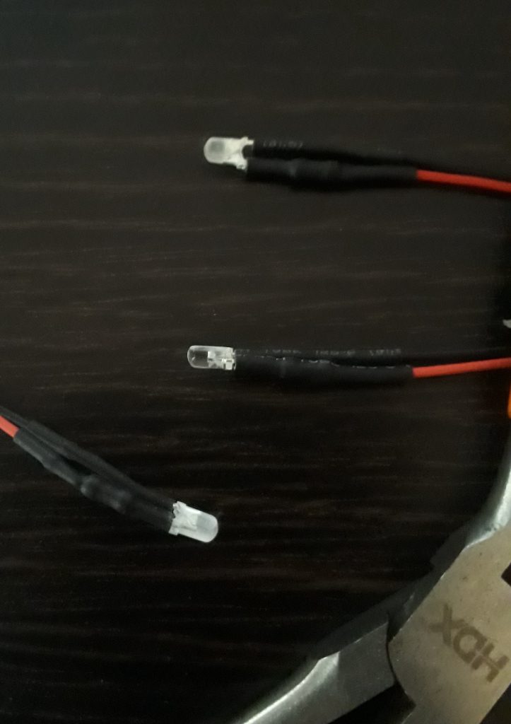
before grinding (center) and after grinding (top and bottom).
(Photo: Apollo Education Experience Project)
Once the three LEDs had been ground down to size, I marked the centers of the three edges of the middle plastic sheet near the rate scales. Then I used a narrow bit on my Dremel/Craftsman tool to grind out rounded slots that matched the LEDs’ shape. I drilled holes just outside the edges of the bottom plastic sheet for the wires. I inserted the wires through the holes and reassembled the faceplate laysers, trapping the LEDs in the gaps in the middle plastic sheet. I routed the wires to the nearest frame post, then zip-tied them to the posts.
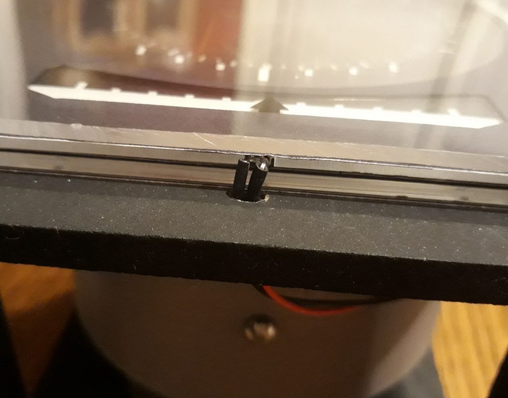
(Photo: Apollo Education Experience Project)
The LEDs have a color that perfect matches incandescent lamps, but they are very bright, so I’ll also need to make provision for some resistors to adjust the brightness. So to allow for external power, internal connections for all the LEDs, and separate resistors for the rate scale LEDs and the “8-ball” LEDs (in case they needed different values), I figured I needed 6 terminals.
I drilled 6 holes along one edge of the base, then inserted 6 screws and fastened them in place with nuts. The two inner screws are mounted so that the nuts are outside, while the others have the nuts on the inside. The three on the left have blue nuts to remind me that they’re negative, and the three on the right have silver for positive. I connected wires inside between the two middle screws and the adjacent screws. After a little testing, I figured 1.5K-ohm resistors would be about right, so I installed 1.5K resistors between the outer posts and the adjacent posts. Finally, I connected the rate scale LEDs to their terminals.
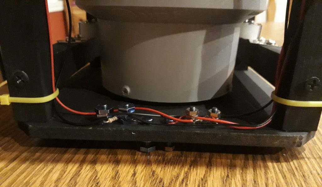
(Photo: Apollo Education Experience Project)
I needed to test to ensure the terminal configuration as well as the rate scale LEDs worked and looked correct. I connected a 12-volt supply to the new external terminal posts, turned out the room lights, and turned on the power. The scales illuminated properly! I did need to adjust the LED for the right-hand scale (it had gotten out of its little niche and was pinched between two sheets of plastic). Now all three scales were illuminated relatively evenly, and looked a LOT like the real thing!
(Photo: Apollo Education Experience Project)
To light the “8-ball” part of the FDAI, I mounted four LEDs on the four posts of the frame, securing them with zip ties. I was careful to align the LEDs so that they were on the inner corners of the posts, then bent the LEDs toward the “8-ball”. I then routed the wires down the posts to the terminals. The two LEDs on the far side from the terminals needed extension wires soldered to them, since the factory-installed leads were too short. I did have to install a couple of extra zip ties to help keep the wires from dangling in view of the faceplate opening.
Once all the LEDs were connected to the terminals, I reconnected a 12-volt power supply to the terminals and turned it on. All LED came on as they should. The electrical portion of the first FDAI is complete!
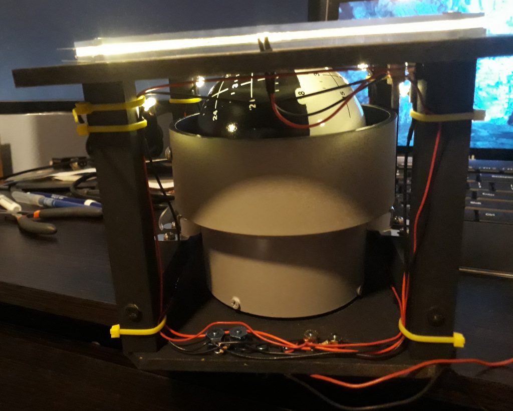
(Photo: Apollo Education Experience Project)
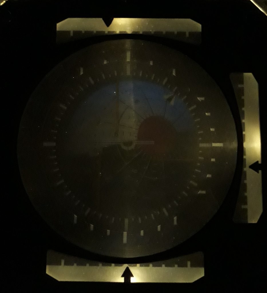
All four of the “8-ball” LEDs and all three of the rate scale LEDs are in place, their wires are all connected to the internal terminals, and a 12-volt supply is connected to the external terminals. Does the result look good? I turned the room lights off and turned the power supply on to see. It looks pretty darn awesome!
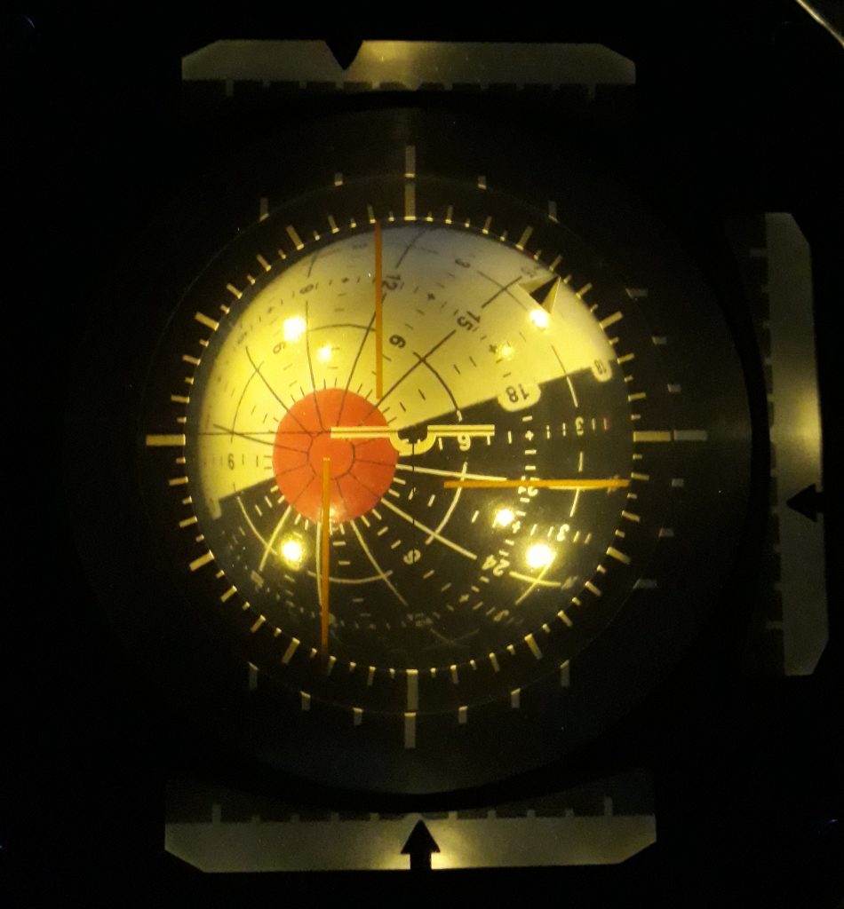
(Photo: Apollo Education Experience Project)
I do think I may need to increase the value of the resistor for the “8-ball” LEDs to about 2.1K ohms, but I’ll do that another day.


