Mission Timer
The mission timer was the first electronic piece I designed and built for the project. The mission timer provided a continuous display of the Mission Elapsed Time, or time in seconds, minutes, and hours from liftoff. Many of the scheduled events during an Apollo mission were directly synchronized with the MET, so the mission timer was a key component.
A working replica of the mission timer needed to keep time, of course, but it needed to do so when requested. Normally, it was triggered by the liftoff, but it could also be triggered by a switch on Panel 2. In addition, in the event the MET needed to be re-entered, the mission timer had a reset switch and momentary switches to manually enter the hours, minutes, and seconds. I plan on modeling all of the manual components.
I started by choosing CD4026 integrated circuits to drive each digit. These combined a counter with a 7-segment decoder/driver in a single IC, which would cut the resulting chip count nearly in half. I built a prototype circuit on a breadboard to test not only the count, but also the reset of the tens digits for seconds and minutes when they reached 5. I was also able to test setting the digits via a two-position momentary switch (one direction for ones, the other for tens, and center off). I provided the clock pulse with a simple 555 circuit. Although a crystal would be more accurate, that level of accuracy wasn’t really necessary.
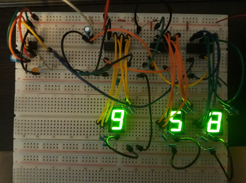
(Photo: The Apollo Education Experience Project)
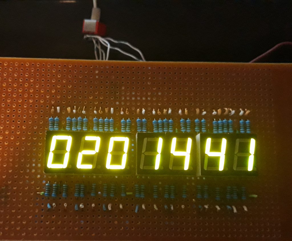
The test circuit had only three digits, but that was enough to test with, since the remaining digits would be identical. I built out a display board with the full 7 digits (3 for hour, 2 for minutes, and 2 for seconds), with a slight gap between each group. There were no colons separating the digits, only spaces, and each group would be labeled on the acrylic panel overlay anyway. I provided connectors on the rear of the board that will connect to the logic board.
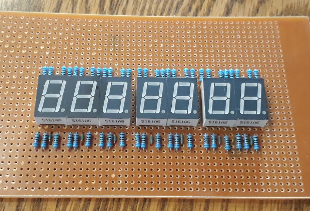
(Photo: The Apollo Education Experience Project)
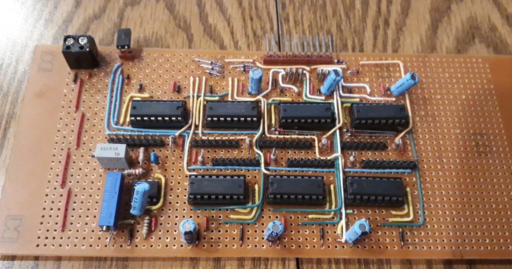
Like the display board, I built the logic board on a prototyping PC board. While this did ease construction in some respects, I did have to do a fair amount of wiring as compared with a custom PC board. But since these are likely to be one-off items, the time and expense of custom boards would not be worth it. Also, to protect the CMOS chips from possible excess heat during soldering, I socketed all of the ICs except the 555. I also provided capacitors for all but the hundreds digit of the hours to help debounce the switch inputs for setting them.
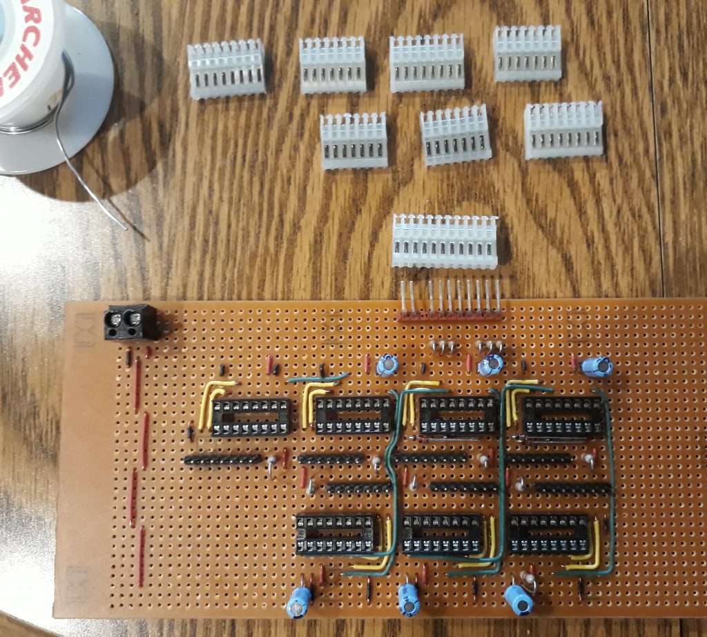
(Photo: The Apollo Education Experience Project)
In addition to completing the wiring, I added a couple of diode networks to serve as gates for resetting the tens digits of the seconds and minutes. If the output of the chip tries to go to 6, it will send a signal to the reset pin of the chip. I also added another header connected with the common cathodes of all the LEDs, which can either be jumpered for constant full brightness or connected to a potentiometer for variable brightness. Finally, I installed a multi-turn trim pot for precision control of the output from the 555 timer circuit.
I connected the display board to the logic board for the final test. I also connected a DPDT switch to one set of inputs (the hours’ ones and tens digits), and applied power. It works! I tweaked the trim pot to get an accurate count of seconds across a couple of minutes, and the circuit was complete.