
CM Framework Construction – Part 2
After well over a month of delays, I’m finally making progress on the construction of the CM itself. I had been trying to find a makerspace with a CNC machine large enough to take a 4′ x 8′ sheet of 3/4″ plywood. I located one that was relatively close, but their CNC couldn’t handle the size. They had a supporting member with his own CNC that could handle 8 feet in length, but only 30″ in width. I did some rearranging of the drawings on my computer to get everything to fit in 30″ or less, but I couldn’t get the manager of the makerspace to put me in contact with the CNC’s owner. I finally gave up, but not before falling way behind.
Without a CNC, I had to cut the plywood pieces by hand. Rather than attempt to draw everything out by hand as well, I enlarged the files and had the Print Services shop at the Johns Creek Staples (a new partner to the project) print them out actual size. I transferred these to the plywood and started cutting away.
The first piece to go on was the center of the crew cabin floor. This was necessary since the angled supports for the rest of the floor snug up against the edges of this piece. I marked the locations of the structure underneath so that I could screw it in place and hit the centers of the boards rather than skim the edges of them with the screws. Once marked, I glued the floor in place, drilled pilot holes for the screws, then screwed the floor to the structure, countersinking all of the screws. I’ll later fill in the holes to make the floor smooth.
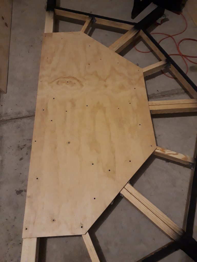
(Photo: Apollo Education Experience Project)
Now for the support structure for the rest of the floor. The real CM had a concave curved floor. I decided that would be too difficult to model, so I opted for a “faceted” floor. Turns out that was still pretty difficult! The angles for some of the pieces were a real pain. The main pieces weren’t so bad – they had a 15-degree angle at one end and a 45-degree angle on the other. Like the first part of the base, I doubled-up on the main beams for extra strength since they were load-bearing. I installed these first with screws at the 15-degree end into the support structure, then some support blocks at the end of the base structure, and fastened everything with tie plates. The four in-between beams had the same angles, but these required a notch on the top side to allow for the geometry of the plywood “facets.” I fastened these in place similar to the others, but because they didn’t have a corresponding base beam I used an extra tie plate per board.
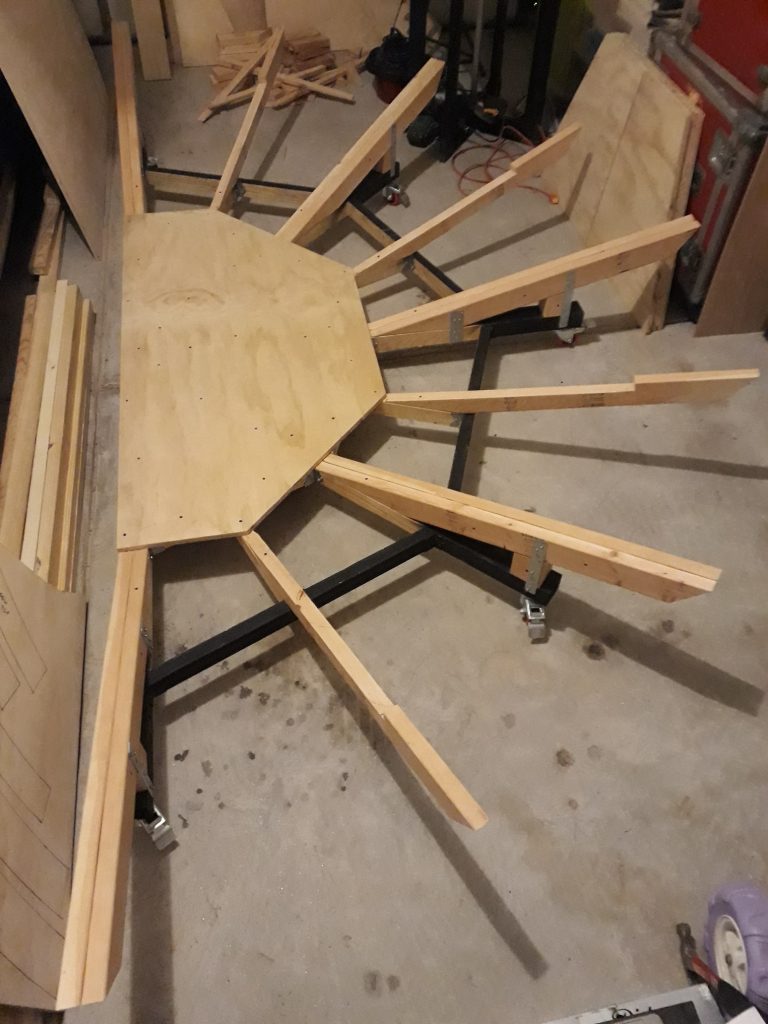
(Photo: Apollo Education Experience Project)
Next came two tiers of cross-bracing. Here’s where the angles really started getting goofy. Good thing I was able to get a really great deal on a compound miter saw at the Brookwood Home Depot! I would never have been able to cut these pieces without it! Even with it, though, I found that there is simply a lack of precision working with these kinds of tools and materials. While I managed to get the angles more-or-less correct, the lengths gave me trouble. It’s really amazing how even a tiny difference in length gets amplified when angles are involved. As a result, some of the inner bracing was a little off, but it still worked. I was more careful with the outer bracing. All of the bracing was installed with angle brackets and coarse-thread screws. I doubled-up on one pair of outer braces because these will help transfer some of the load of the couch supports.
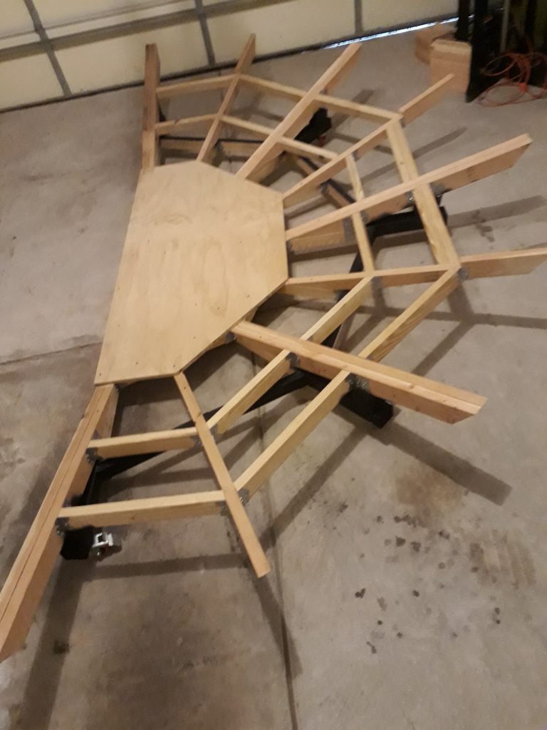
(Photo: Apollo Education Experience Project)
Now for the rest of the flooring. Before starting the flooring, I applied some more flat black to the base to cover the additional bracing added for the floor supports. Working from the seam edge (the side that will connect to the other half, I glued each floor piece to the structure, then screwed it in place. The angled edges of the floor pieces fit right into the notches of the single angle support beams. The last piece was the floor under the hatch. The fit was just a little too snug, so I shaved a sliver off of each of the angled edges with a circular saw, increasing the angle by, oh, I don’t know, maybe a quarter of a degree. But whatever the angle, it fit great. I glued and screwed it in place, adding a few additional screws in the double beam outer brace.
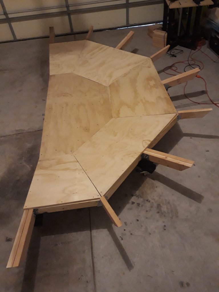
(Photos; Apollo Education Experience Project)
My original intent at this point was to install the circular “girdle” and start work on the conical structure of the CM. However, after the issues I had with the angles, I thought it might be best to finish the other base and work on the top structure of both concurrently so I could check fit during the construction to ensure the two halves would go together properly. I’d really hate to be surprised by misaligned halves that won’t go together without a big gap! So, I have all the materials for the second base and have gotten started on it. More coming soon!


