
Entry Monitor System (EMS) – Part 3
Now that the circuit design was complete, I needed to translate it from the breadboard to a permanent circuit board. Prototyping circuit boards are usually pretty expensive, but I got a stack of them from an eBay seller for a decent price. Good thing, too, because it looked like the EMS electronics would need several of them. After studying the layout of the EMS and the breadboarded circuit, I figured the finished circuit would need to be on four boards: the main logic board, the counter display, the corridor light display, and the graph display.
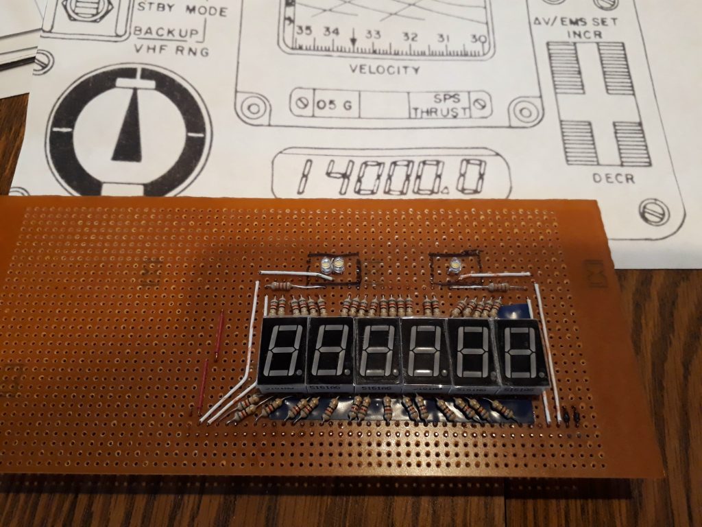
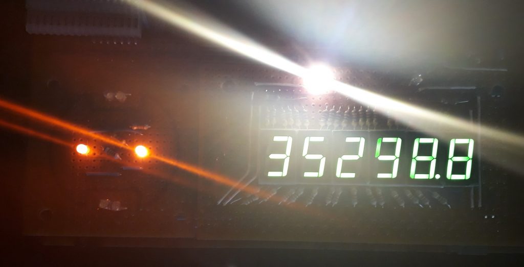
I started with the counter display board. I installed a 42-pin header on the copper side of the board to eventually plug into a 42-pin socket on the yet-to-be-built logic board. On the component side, I installed the six 7-segment displays approximately centered with the header. I connected all of the common cathodes to the ground bus on the copper side, and applied some electrical tape over the connections on the components side so as not to accidentally make shorts when installing the resistors. The resistors for the segment pins on the bottoms of the displays I connected directly to the headers, but the ones on the tops I connected to the next row of pads and jumpered the pads to the headers on the copper side. The breadboarded circuit had only 5 counters and 5 digit but the final circuit needed a sixth digit. I installed the sixth digit in the tenths position and hard-wired all the segments except for “G” (the center segment) to positive, along with the decimal point of the ones digit. I paired the “G” segment to the “G” segment of the ones display so that when it started counting down the segment would flicker and give the illusion of counting rapidly.
I also put the “.05 G” and “SPS Thrust” lights on this board, even though they might logically be part of the graph board. The “.05 G” light actually has two LEDs – one for the actual indicator and one to light for the test mode. Making the test mode and the active circuit use the same LED would have required some complicated wiring and maybe another chip – using a second LED was FAR easier.
(Photo: The Apollo Education Experience Project)
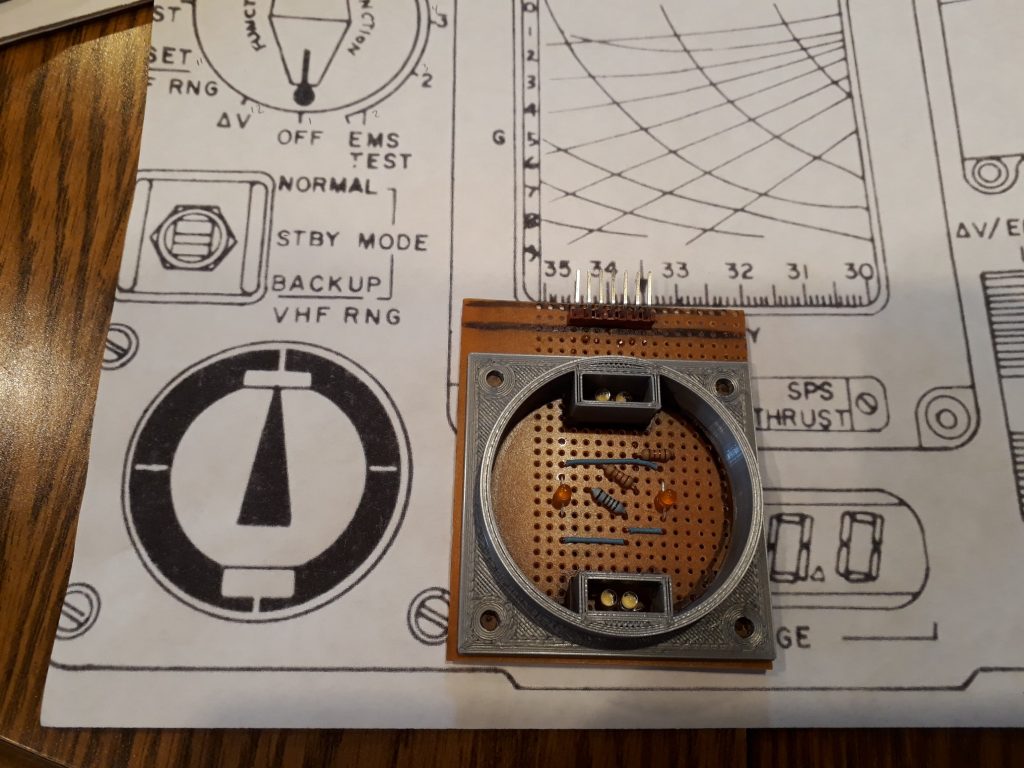
The corridor light display was next, mainly because it would be really simple and easier to finish than the display board was. By this time, I had trimmed the display board down to size, so I had a scrap piece that was suitable for this circuit. I traced the 3D printed gauge insert onto the board to accurately place parts, since the “up” and “down” lights would have pretty tight spacing. Like the “.05 G” light on the display board, the “up” and “down” corridor lights each used two LEDs – one for the active circuit and one for the test indicator. In the center, I installed two amber LEDs to serve as backlight for the corridor orientation gauge. All of these I wired to a 7-pin header at the top of the board for connecting to the main logic board.
(Photo: The Apollo Education Experience Project)
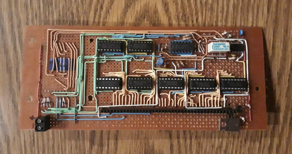
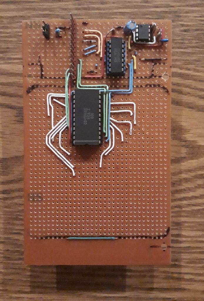
Now for the hard part: building the main logic board. I knew the position of the header socket based on the header for the display board, but I had to put some thought into placement of the remaining circuitry. Five of the chips were easy – the three counters for the ones, tens, and hundreds digits and the 7-segment decoders for the thousands and ten-thousands digits. These needed to be placed near the header socket. In retrospect, I should have oriented the decoders differently, because I wound up having to route all the wiring around those two chips. Oh, well. The two remaining counter chips were also easy – aligned with their respective decoders. The flip-flop, relay, and 555 had to go in the remaining space, but where? After thinking about how everything would fit together, I decided to place the connectors to the corridor light board, the graph board, and the 12-position switch all on the left, leaving the right half of the top row for the remaining pieces. But it was not just the two chips and relay – it was also the small pile of diodes used for handling the logic of what gets activated when the switch is in each of the 12 positions. After nearly half a dozen schematic drawings, I found that I could place some of the diodes near the switch headers, reducing the number needed near the other components. I settled on an arrangement, then started soldering.
I soldered the 555 directly to the board, but I socketed all of the CMOS chips so they wouldn’t be subjected to the soldering iron. Once the major components were in place, I meticulously translated the circuit routing from the breadboard to the logic board. Whenever possible, I used the diodes and other discretes as jumpers to reduce wire count, but as you can see there are still PLENTY of wires. I had intended to perform testing during the assembly process (one reason for building two of the display boards first), but found that everything is so inter-connected that it really wouldn’t work until the whole thing was practically complete.
I made a few minor on-the-fly modifications to the circuit. One was adding a small header so that I could use a jumper to set the LEDs at a fixed brightness or connect a pot to set a variable brightness. The header feeds a Darlington transistor pair that controls the common cathode bus – the second transistor is a TIP30 power transistor. Another was how the relay would be triggered. I originally intended the relay to be controlled directly from a spare digital output from the Arduino in the Open DSKY, but changed my mind to have the DSKY’s spare outputs trigger reed relays on a daughterboard expansion. But since the relay on the logic board has a 4.5-volt coil, I needed to power it somehow. I installed a header that the contacts of a reed relay can be connected to, which connects the main board relay’s coil to positive thru a voltage-dropping resistor (the EMS will be powered by 12 volts).
(Photo: Apollo Education Experience Project)
Now that I had enough pieces to test the circuit, I assembled them and powered them up. It worked … sort of. Given the number of wiring connections, it was inevitable that a few were either incorrect or missed. I did have to swap a pair of wires driving segments of a digit, and add a couple additional lines from the switch header to various control points.
(Photo: Apollo Education Experience Project)
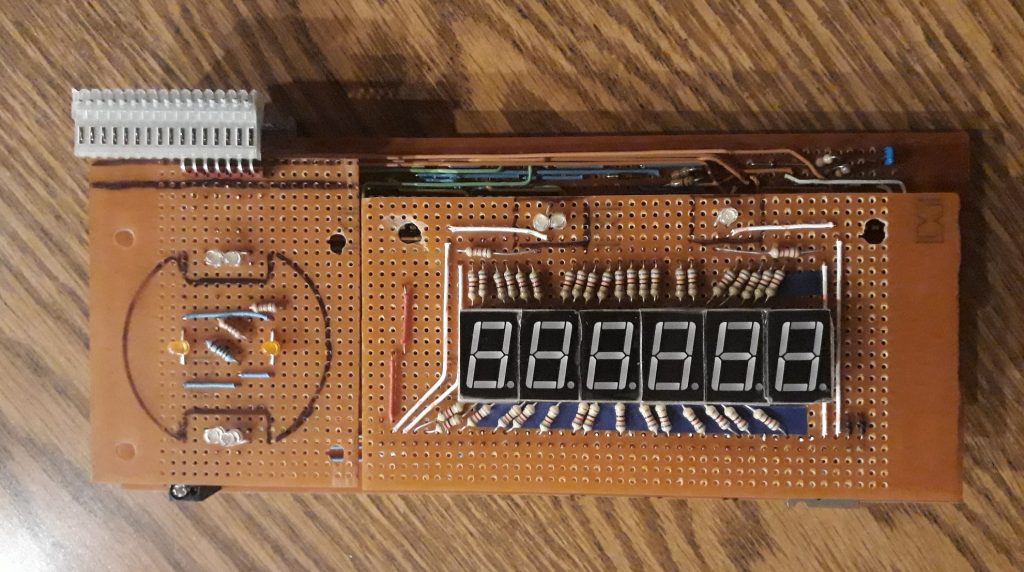
Once I completed the fixes, I reassembled the 3 boards and powered it up for another test. It worked great! I cycled through all 12 positions of the switch, and everything worked as it should. Everything, that is, except for the “up” and “down” corridor lights – while the test LEDs for them worked, the circuitry to drive the active LEDs will be on the graph display board.
(Photo: Apollo Education Experience Project)
The final electronic piece of the EMS was the graph display board. This was rather difficult to think up, since my intent was to simulate the electroluminescent (EL) backlight using some green LED while replicating the G-force reading with amber LEDs. I settled on a two-layer implementation – the green LEDs would be mounted very close to the board while the amber LEDs would be mounted as far from the board – and as close to the overlay – as possible. To do this, the LEDs would need to be mounted on the copper side.
I started by arranging the header for the ribbon cable and the ICs, then soldering them in place once I was happy with the arrangement. Again, I socketed the CMOS chips but not the 555. Then I started installing the discretes and the wiring. When I was nearly done, I realized I had made a minor orientation mistake – I meant to place the ribbon cable header on the side nearest the corresponding connector on the main board, but I put it on the opposite side instead. Not a game changer, but it reinforced the need to pay attention to little details when building a circuit in 3 dimensions.
(Photo: Apollo Education Experience Project)
I flipped the board and started installing the amber LEDs, ensuring that the tops of the LEDs were as even as I could get them. I also placed the first and last LED such that they would be aligned with the zero G-force line on the display screen. I chose not to install the green “backlight” LEDs at this time in case I needed to make corrections on the board. I can always install them at a later time.
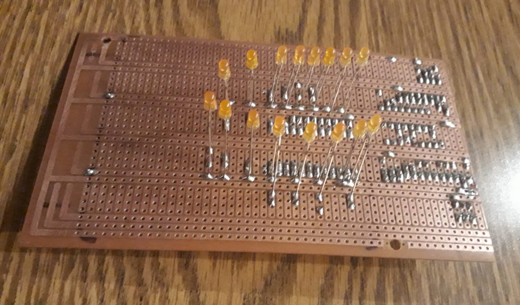
(Photo: Apollo Education Experience Project)
I connected all four boards and powered them up for a test. This time, things didn’t work well at all. The counters still loaded and counted down, but the various LEDs did not light correctly. The active “up” and “down” corridor lights came on with nearly every switch position EXCEPT the one they were supposed to! And several of the other LEDs – including the gauge backlight – came on with the wrong positions as well. I went through much thinking, puzzling, and comparing the assembled circuit with the breadboard, and as best as I could tell everything was wired correctly.
I don’t know what made me check, but I decided to view the orientation of the active “up” and “down” corridor LEDs – they were installed backwards! I wondered how that might have happened, then it occurred to me – they’re wired to a common lead. Since most other LEDs in the circuit are wired common-cathode, I did the same with these, when they should have been common anode. But they’re not connected directly to a power source – they’re connected to two different logic sources. Part of the logic is done using diodes, and the LEDs are diodes, so they still lit but they screwed up the logic terribly. I removed them and installed fresh ones, then re-tested – lo and behold, things worked perfectly!


