
Breaker Panels
The real Command Module had literally hundreds of circuit breakers all over the place. These were aircraft-style “push-pull” circuit breakers that could be pushed in to connect a circuit, pulled out to disconnect it manually, or would pop out when tripped. Circuit breakers of this type run around $25 or more each when new, so buying somewhere around 250 of them would be prohibitively expensive on my budget. I do need a few for handling the working functions I’m planning for the CM, and fortunately I happen to have a few of that vintage. Seriously – at least two I have are dated 1969 – one is even from July 1969! How appropriate it would be to include these in the CM!
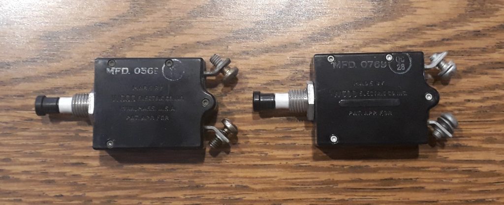
(Photo: The Apollo Education Experience)
For the rest, though, I’m 3D printing just the parts that are visible (the buttons, threads, and nuts). I measured one of the real breakers I have, then modeled the thread and nut as a single part and 3D printed them in silver. The buttons I modeled in two ways – out (off/tripped) and in (on). The “out” version I modeled with a slightly thinner shaft. To indicate when the breaker is off or tripped, the shaft has a white “collar” of a material that resembles heat-shrink tubing. So I bought some white heat-shrink, cut pieces to length, and attached them to the “out” buttons. Then I installed the buttons into the thread/nut bases. Conveniently enough, the “in” buttons were a snap – literally. As luck would have it, after trimming the brim from the buttons, they were a snap-fit and didn’t require gluing. The “out” buttons weren’t the same … after attaching the heat-shrink, they required a drop of CA (cyanoacrylate, or super glue) to attach to the bases. Nearly all of the buttons I printed in black, but I printed a few in yellow for some specialty breakers.
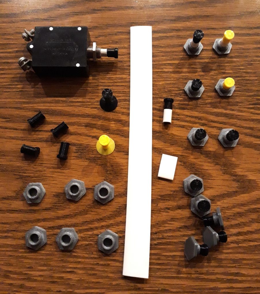
A real vintage aircraft circuit breaker is at the top left for comparison.
(Photo: The Apollo Education Experience)
Since I’ve already build the location for Panel 275, I figured it was as good as any to start with. I thought about attaching the breaker bases first, but masking around them would be a problem, so I painted the panel first. I found a good gray spray paint that is a combination primer and paint to save time. Once dry, I marked the panel using a full-size cutout of the panel, both for locations of the breakers and the screw holes. BTW, this is the panel that will span the seam between the two halves of the CM, so I cut the panel and the template at the seam location.
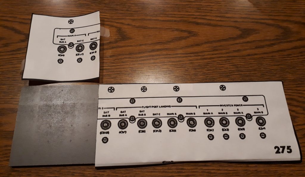
(Photo: The Apollo Education Experience)
I drilled holes for the screws, then proceeded to mount the breakers. Since the panel is now painted, I had to locate a decent glue that works on painted surfaces. I selected what I figured would be an appropriate selection of “in” and “out” breakers (I chose “out” for all of the post-landing breakers since they would not be on in-flight). I placed a dab of glue on each mark, then fastened the breakers. Before the glue dried, I used a straightedge to align the breakers, then set the panels aside to dry.
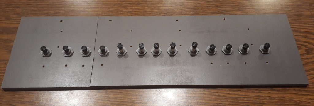
(Photo: The Apollo Education Experience)
Once the glue for the breakers was dry, I mounted the acrylic pieces using #6 screws, and installed additional #6 and #8 screws as appropriate (which will be used to mount the panel in place). I also used some dry transfer numbering to apply the panel number “275”, then hit the corner with a touch of clear to protect it. This panel is ready for installation!
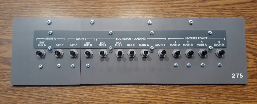
(Photo: The Apollo Education Experience)


