
DSKY – Part 1
Any replica of the Apollo Command Module would not be complete without a flight computer. In actuality, the flight computer itself (the Apollo Guidance Computer, or AGC), was never visible – it was hidden in a rack behind a panel. What WAS visible was a pair of interface terminals called the DiSplay-KeYboard, or DSKY for short. One DSKY was installed in the main control panel, while the other was installed just to the right of the navigation station.
The two DSKY units which will be installed in the replica Command Module are produced by S&T Geotronics ( www.stgeotronics.com ). They provided a pair of complete kits, and will also be providing some custom 3D printed parts for mounting them in the control panels.
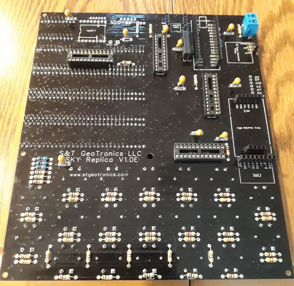
No sooner had I arrived home with the kits in my grubby little hands, I opened one up and started construction. The circuit boards are beautiful and elegant, but this isn’t readily noticeable until time to mount the completed boards in the case, at which time you seen the engineering that went into the layout.
I started by soldering all of the resistors to the board, mostly for regulating the brightness of the LEDs in the keyswitches. After placing all of the resistors, I added most of the other discrete components, mainly capacitors and sockets, but also the power terminal and reed relay.
(Photo: Apollo Education Experience Project)
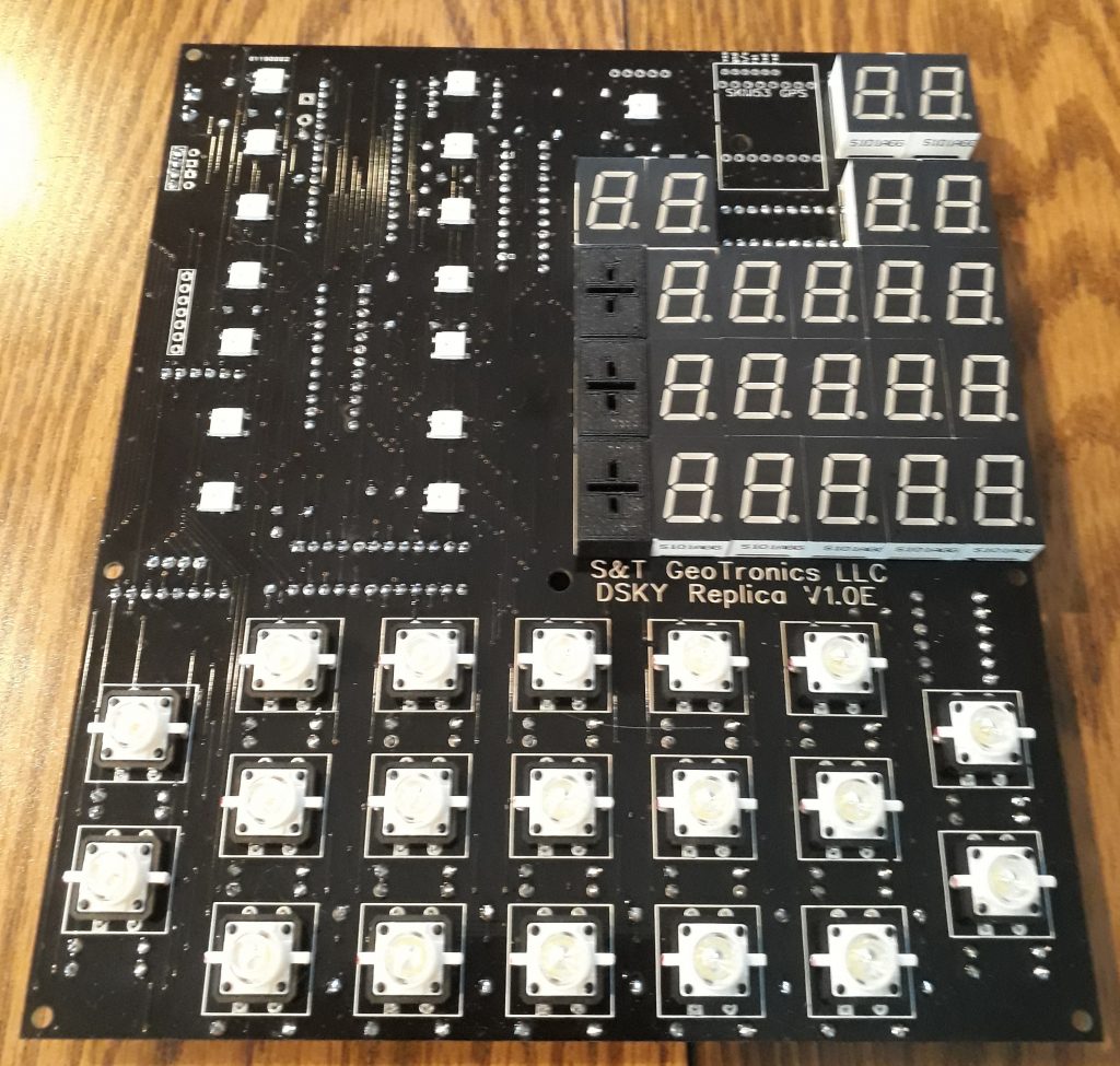
Following the installation of the various discrete components on the back of the board, I flip the board over and start installing the 7-segment LED displays and the LED-lit keyswitches. I also installed the custom +/- LED displays. S&T Geotronics discovered that nobody made LED +/- sign displays any more, save for some company in Israel. So out of necessity, they designed and fabricate their own +/- displays.
(Photo: Apollo Education Experience Project)
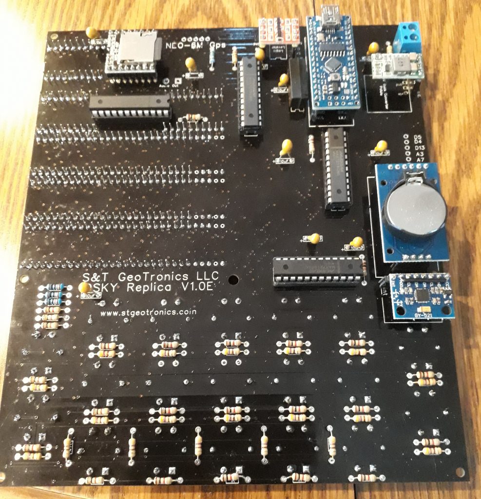
The S&T Geotronics DSKY comes packed with a lot of cool stuff. It is Arduino-based, so it is powerful and customizable. But the hardware includes some nifty gadgets, including a real-time clock (RTC), an intertial measurement unit (IMU) (and this one won’t get gimbal lock!), an MP3 player for playing interesting sound clips (such as “We choose to go to the moon in this decade and do the other things…”), and a GPS. Yeah, yeah, I know – the real DSKY / AGC didn’t have that stuff. But that’s OK – this is for fun and educational purposes. These things can be incorporated into the exhibit, presentations, and lesson plans. But anyway…
Most of the modules come without their headers installed. So I trim some header material (included) to the right lengths and solder them to the modules. Most of the modules are socketed, but a couple need to be soldered to the board. One of these is the MP3 player/SD card reader – it’s up at the top left. Once all the soldered components are in place (except the keyswitches – they’re friction-fit for now until after the lamp test), the various modules and integrated circuits are installed in their respective sockets.
(Photo: Apollo Education Experience Project)
Once everything on the back is in place, I installed the GPS module on the front up by the top two 7-segment LED displays.
(Photo: Apollo Education Experience Project)
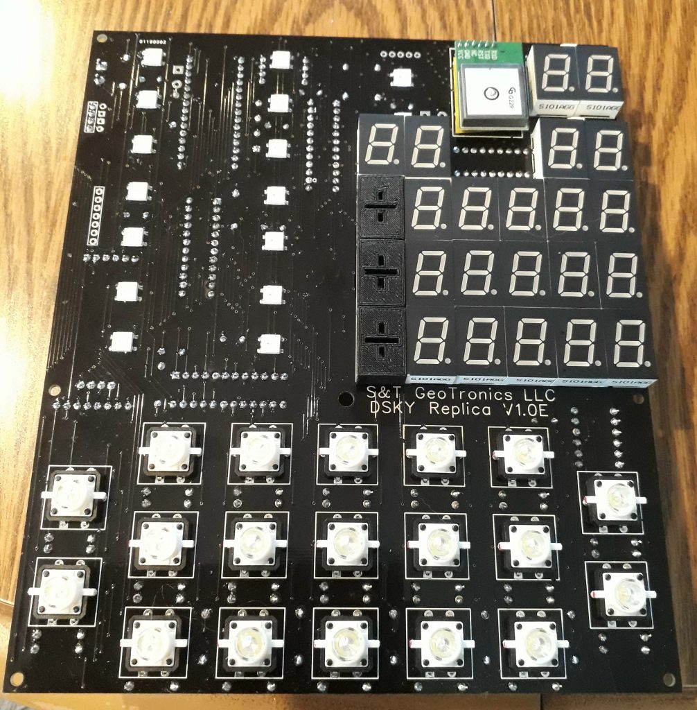
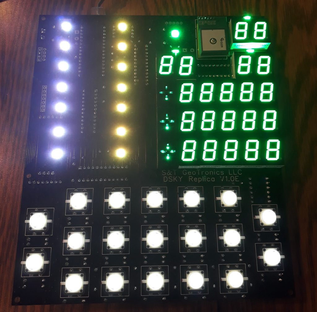
With everything in place, it’s time for the lamp test! This is the first chance to see if everything works OK. The only real concern I have is the LED keyswitches. I could connect up the battery pack and test it that way, but since the Arduino can be powered thru a mini USB connector I do that by connecting it to my laptop’s USB port. All the keyswitches light! (*whew*) Then to run the Lamp Test program I enter VERB 35.
The AGC was given instructions using a “Noun-Verb” structure, as well as a simpler “Program” (PRO) structure. To enter a command, you would press “VERB” followed by a two-digit code, followed by ENTR”. If that Verb needed a NOUN to act upon, you would press “NOUN” followed by another two-digit code, followed by ENTR. To run a program, you would press “PRO”, the number, then press “ENTR”.
The lamp test (and indeed all of the useful/interesting commands on the S&T Geotronics’ DSKY) use the same “Noun/Verb” structure. In the case of the lamp test, it’s just a VERB. When you do this, every LED and every segment is supposed to light up. In my case, it does! Lamp test passed.
(Photo: Apollo Education Experience Project)
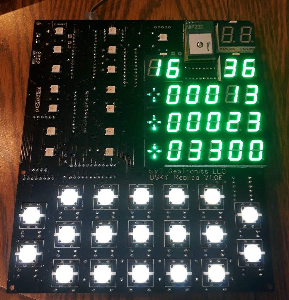
Now that I know that the lights and keyboard are working and have soldered the keyswitches in, I can test the functions of the DSKY (well, everything except the audio since the speaker isn’t attached yet). The keycaps are missing, so I had to refer to a photo of a DSKY keyboard so I could press the correct keys. The functions I tested were:
VERB 35 ENTR — Lamp Test (this is what I just did)
VERB 16 NOUN 17 — Display the values from the IMU (Inertial Measurement Unit)
VERB 16 NOUN 36 — Display the time from the RTC (Real-Time Clock) (seen in this photo)
VERB 16 NOUN 43 — Display the current longitude and latitude from the GPS
VERB 21 NOUN 36 — Set the time on the RTC
(Photo: Apollo Education Experience Project)
I had to look up my location’s coordinates to check the GPS. Darn if it wasn’t right! I also tested the IMU by moving the board around and watching how the numbers change. Neat stuff!


