
FDAI (or “8-Ball”) – Part 3
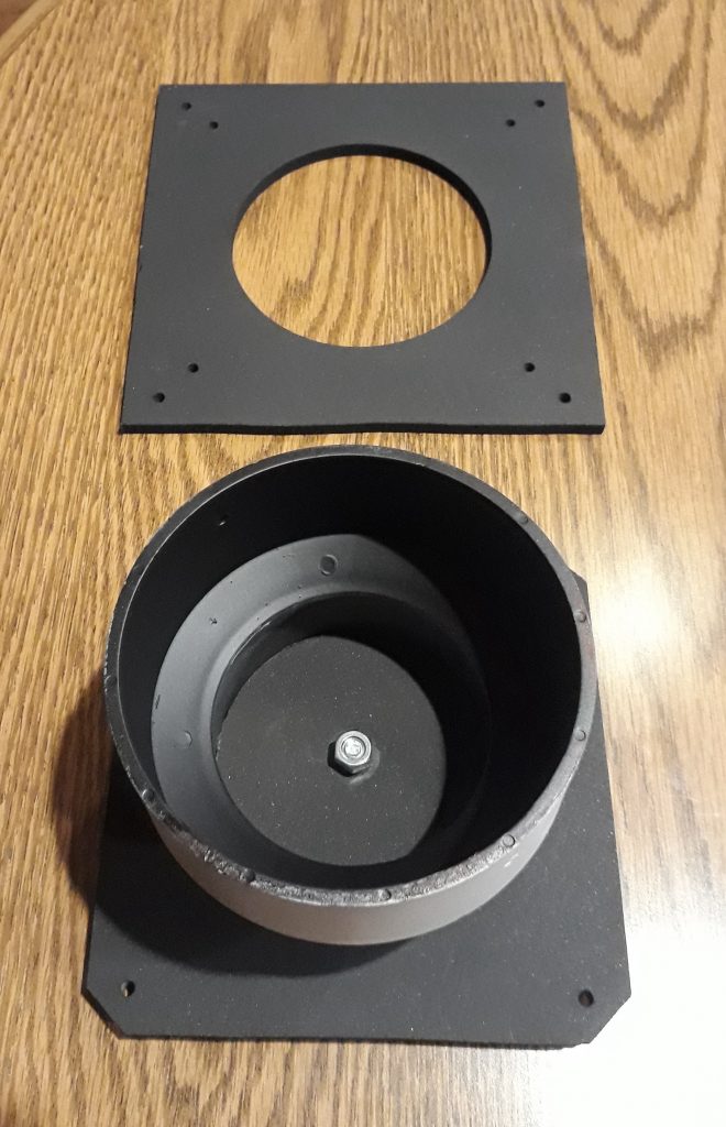
The “8-ball” in my FDAI replica has one degree of freedom of movement within the PBC “yoke.” Now to give it a second. I used a hole saw to cut a circle out of a piece of MDF which was just the right size to fit in the 3-inch side of the yoke. I held it in place with four #4 wood screws. I then painted the inside of the gimbal with a layer of primer followed by flat black. I left the outside just primer.
The small hole cut by the hole saw’s pilot is just the right size for a small bolt, which will mount the gimbal to the base of the FDAI. This will serve as the pivot point for a roll indication to go along with the yaw indication permitted by the two screws in the poles of the ball (removed in order to paint the gimbal). I also painted the screws themselves flat black as well. Anything which might be visible thru the faceplate needs to be flat black to help enhance the illusion.
(Photo: Apollo Education Experience Project)
Before mounting the gimbal on the base plate, I painted both MDF plates flat black. I mounted the gimbal to the base plate using a 1/4″ bolt, placing two washers between the gimbal and the base, and attaching it with a nylon locknut from the inside of the gimbal. I tightened the locknut JUST to the point of allowing the gimbal to swivel but minimizing the side-to-side movement. Unfortunately, I could not eliminate the side-to-side movement completely.
(Photo: Apollo Education Experience Project)
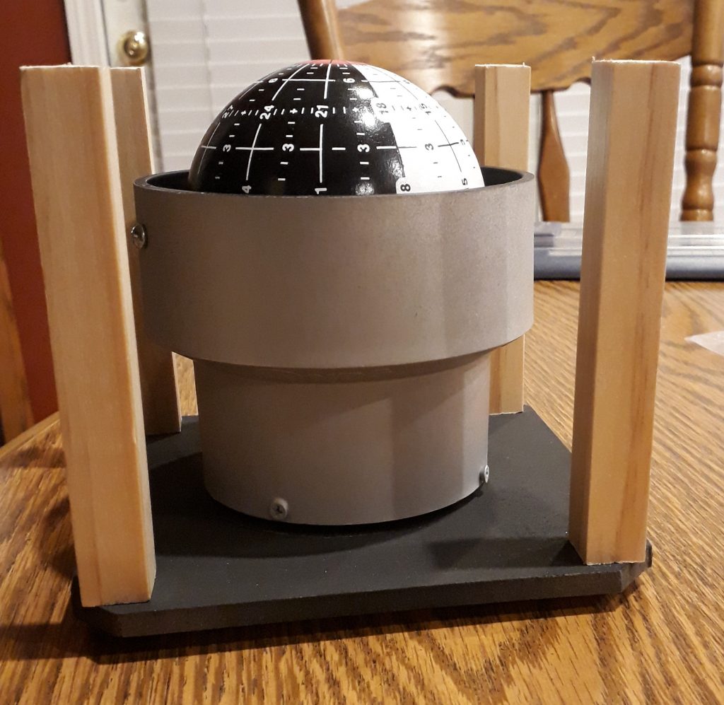
The pitch/yaw indicator (the little crosshairs with the little white “wings”) sits very close to the “8-ball” itself. So to measure the correct height of the frame, I held the assembled faceplate over the assembled gimbal and “8-ball”, then measured the height between the two MDF plates. Using this measurement, I cut out four lengths of 5/8″ x 5/8″ wood I got from the Brookwood Home Depot store. I marked and pre-drilled both ends of each piece to ensure the screws were centered, then mounted them to the base plate.
(Photo: Apollo Education Experience Project)
You may notice that the “8-ball” has more markings than before. I ordered some 1/64″-wide dry transfer stripe decals, and applied the remaining markings to the ball. Well, to a portion of the ball, anyway. Although my FDAI has 2 degrees of freedom to roll and yaw, I decided to fix it in one place since it wasn’t going to be functional anyway. And marking only the visible portion took less time than marking the whole thing.
I hadn’t considered this before, but knowing that this assembly would have to mount flush with the back of the control panel, I needed to countersink the faceplate screws. Since the top layer was plastic, I thought this might be an issue. However, it turned out not to be. Instead of using a regular drill bit, I got a special countersink bit that was essentially a metal plate in the shape of the hole I wanted. The advantage would be that the metal would be in contact with the plastic for as little time as possible, creating as little friction as possible, and reducing the chance of melting the plastic. The drilling went perfectly, and the screws countersunk very well – nearly smooth with the top surface of the plastic.
(Photo: Apollo Education Experience Project)
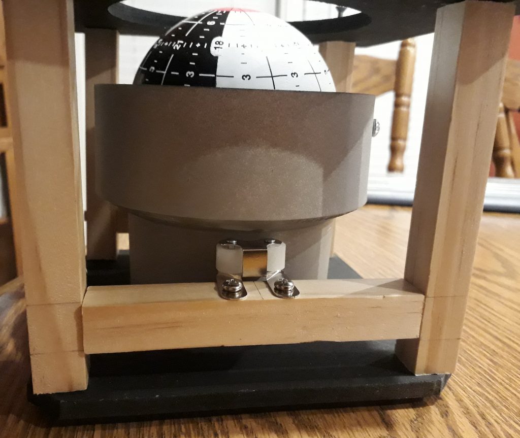
As I mentioned earlier, tightening the mounting bolt for the yoke didn’t completely eliminate the “wobble.” So to help get rid of the last of it, I came up with this addition to the framework. I cut a couple more pieces of the 5/8″ x 5/8″ wood I had left over from cutting the frame, then mounted them on opposite sides of the gimbal between two frame legs. Then I bought a pair of cabinet latches (like you might see in the kitchen or bathroom) from the local Brookwood Home Depot store. I mounted one on each of the new braces, exactly centered and with the rollers just touching the gimbal so that it was free to turn but not free to wobble. I could have installed four of these to stop the wobble in both directions, but the double roller actually helps with the lateral wobble as well.
The braces have a tendency to turn a bit due to their being mounted with only one screw per end. This can occasionally cause the rollers to lose contact with the gimbal, which in turn lets the wobble return. I plan on adding some hobby plywood pieces to the sides to finish it out and block light (yes, lights will be added in a later step), so these can prevent the braces from rotating once they’re in place.
(Photo: Apollo Education Experience Project)
I took my original needle file and printed it off on a transparency, but quickly noticed several things. First, colors are different. Although the color of the needles printed on paper matched the reference photos, the transparency version was WAY darker. So I modified the graphic and re-printed. Better, but the next thing I noticed was that the needles were transparent. I guess it’s supposed to be that way, so it can show up on an overhead projector as the color and not just a shadow. But that wasn’t going to work. The solution was to apply some of the white dry transfer stripe decals to the back of the transparency behind the needles. This not only made them opaque, but brightened the color.
The third thing I noticed was that the roll indicator needle wasn’t going to work on a transparency. The roll indicator is actually black and white. My inkjet doesn’t print white. I have an old Alps 1000 which DOES print white, but I would have to dig out my old Windows 2000 computer to use it, since I haven’t been able to find any Alps 1000 drivers for more recent versions of Windows. But the roll indicator is small and thick, so I tried cutting it out. It did not curl much at all, so this would work. I attached the roll indicator to the back of the roll scale so that just the pointer piece was visible from the front.
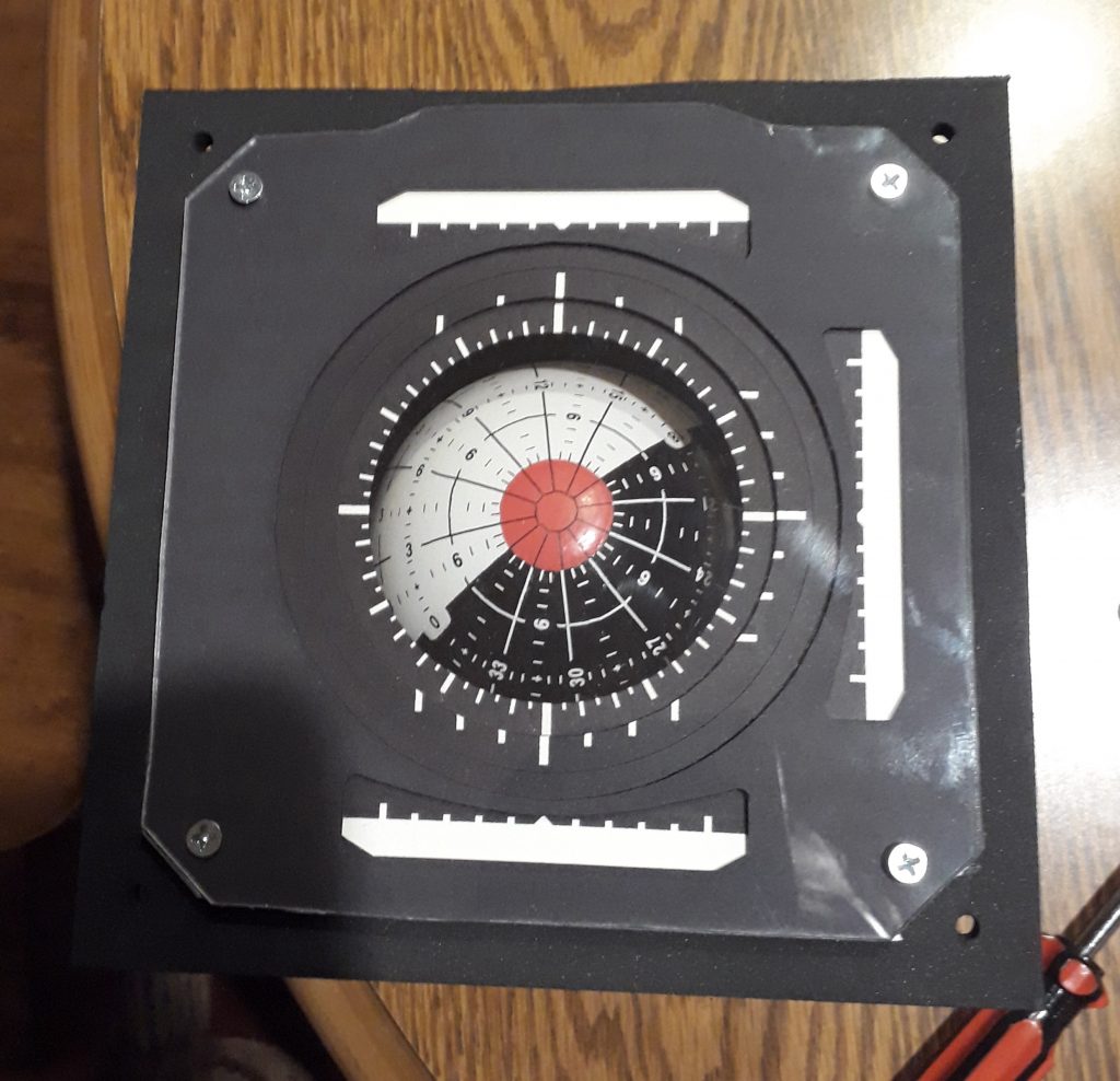
One thing I had not yet tried printing was the pitch/yaw index. I created a graphic with a crosshair 2 pixels wide, then printed that on a sheet of transparency film. I then applied some white dry transfers to the back with the stripes centered on the hairlines. The round part of the index I created by taking a letter “O” from a different sheet of dry transfers, cutting it in half, and placing it appropriately. Using stripes the same thickness as the letter made the whole thing just blend right together. In the meantime, I had also painted the bezel gray (well, primer) to match a real FDAI housing.
Now I assembled the entire unit. The faceplate layers from back to front are:
pitch/yaw index transparency,
roll scale (with roll indicator attached from the back),
error needle transparency,
plastic,
error scale,
rate scale,
plastic,
rate needle transparency,
top baffle,
plastic, and
gray bezel.
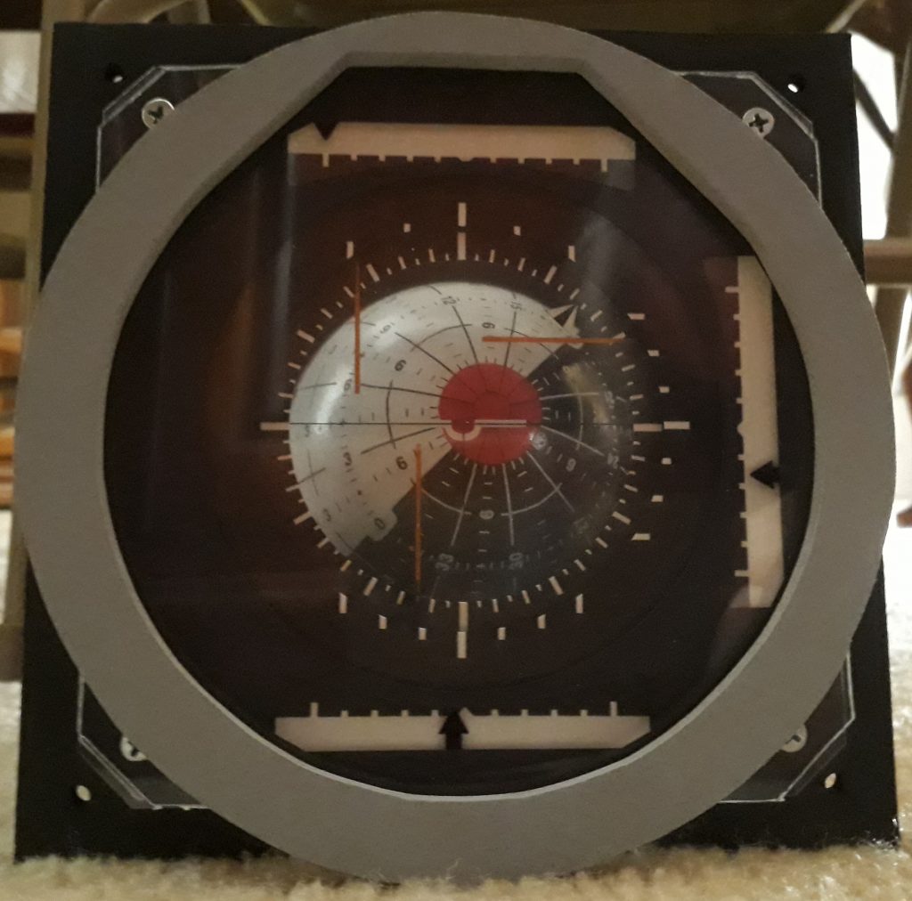
(Photo: Apollo Education Experience Project)
Looking AWESOME!! But it is rather hard to photograph – the plastic is VERY reflective, and it’s hard to get a photo of the whole thing without reflections blocking the view. I’ll have to set up a black backdrop and side lighting or something to get a better photo. But as you can see, the results are looking excellent!


