
FDAI (or “8-Ball”) – Part 2
While waiting for the 1/64″ stripe dry transfer decals to arrive, I started work on the face of the FDAI. At first, this looked like it would be really hard, but after a bit of study and thinking I realized it was just a bunch of layers. So, after figuring out what each layer consists of and what order they go in, I designed some full-scale graphics based on the markings on the face of the actual FDAI. From what I figure, there are four layers of black, a layer with the pitch/yaw indicator, a layer with the roll indicator, a layer with the three error needles, and a layer with the three rate needles.
In the photo below, the four layers of black are (right to left, top to bottom): the roll scale, the error scales, the rate scales, and the top baffle. The print at the bottom right has the three rate needles and the roll indicator (left). As you can see, the center circles get progressively larger, which when removed will allow the scales on the layer below to be seen. The top baffle will also have three openings for the three rate scales and their needles.
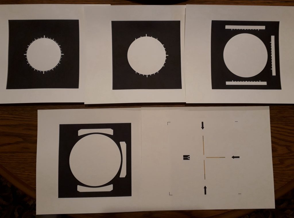
(Photo: Apollo Education Experience Project)
Once the layers were printed, I cut out the centers with a very sharp hobby knife. In addition, I cut out the three openings for the rate scales on the top baffle. One thing I noticed after this was done, was that the paper on which these were printed is white. Well, duh! But what I hadn’t considered is the thickness of the paper – I was printing on 65-pound cardstock, which is thick enough so that the white of the cut edges is visible. So, I took a sharpie and touched up all of the cut edges. I had to do this VERY carefully, because the white indices of the scales come all the way to the cut edges. I did NOT touch up the edges where the indices were for fear of spoiling them.
Something else I noticed is how the paper curls after being cut. I think this has to do with the bias of the fibers in the paper or something. But whatever it is, I realized I could not cut the needles out like this. If I did, they would curl completely up like a noodle or something. It was at this point I decided on a different approach for the needles – printing on transparency film. So I ordered a package of FastPositive inkjet transparency film.
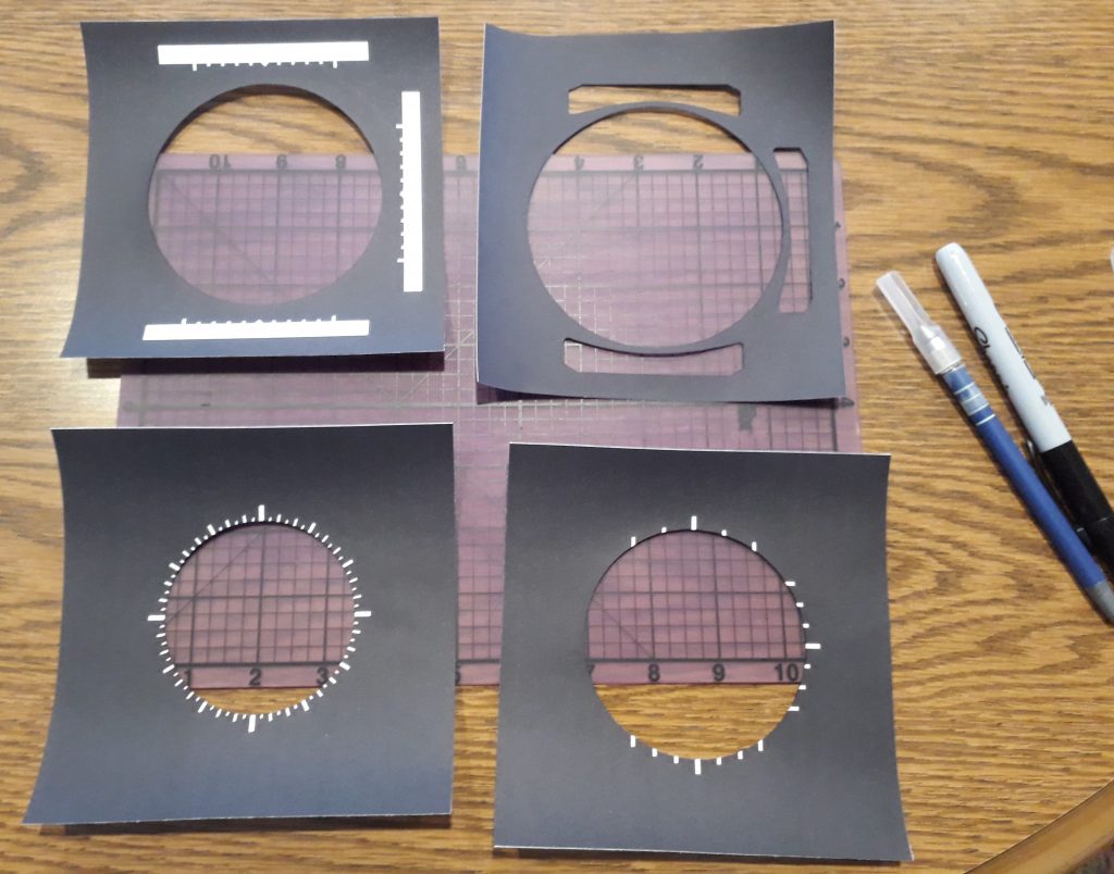
(Photo: Apollo Education Experience Project)
Now that all of the black layers have been corrected, printed, and cut, and all three layers of 2mm plastic have been cut, I assembled the faceplate layers for the first time. From bottom to top, the layers are: roll scale, plastic, error scale, rate scale, plastic, top baffle, plastic. The depth effect looks great! Notice the top edge of the top layer of plastic – it has a bulge. That is because the opening in the front of the FDAI housing isn’t a circle but an oblong shape. If I were to cut the plastic square with the other layers, the edge would be visible thru the housing opening.
The MDF plate is larger because I will need the extra width and height in order to provide mounting points for installing it in the control panel. This is also why the corners of the plastic have been bobbed – to clear the mounting screws.
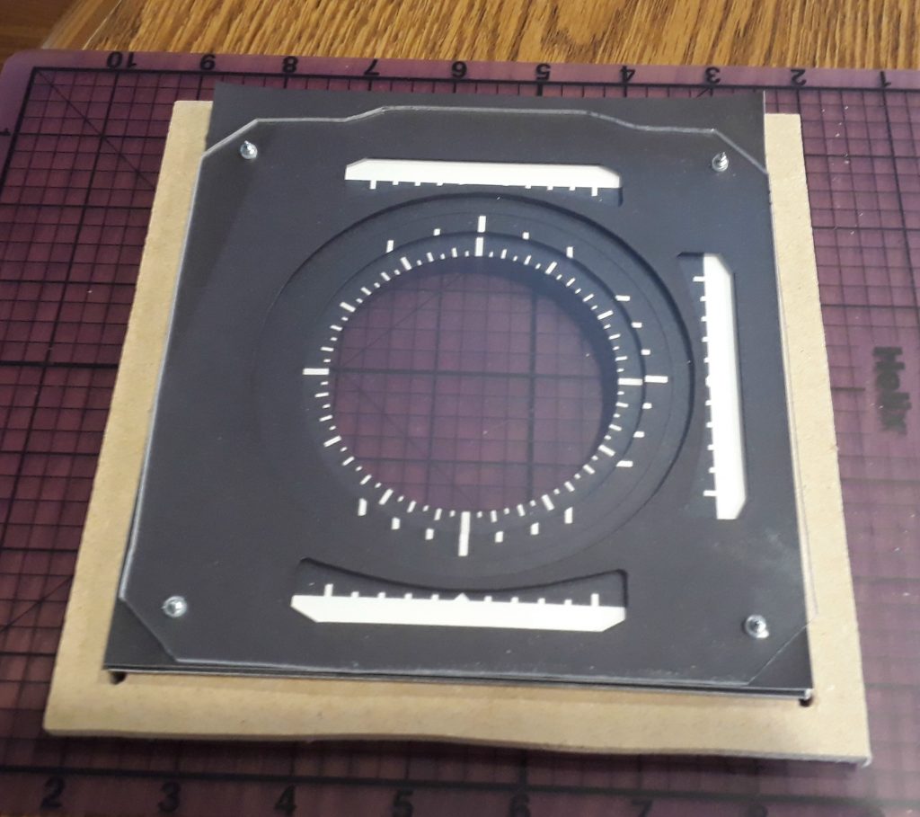
(Photo: Apollo Education Experience Project)
Now to see what it looks like with the 8-ball itself. I’ve cut out the bezel which goes on top of the faceplate, put it on top of the faceplate stack, then held it over the “8-ball” in its gimbal to see what it looks like. I have to say, this is turning out FAR better than I really expected it to. I was thinking that this was going to turn out looking rather cheap, but instead it is turning out surprisingly well!
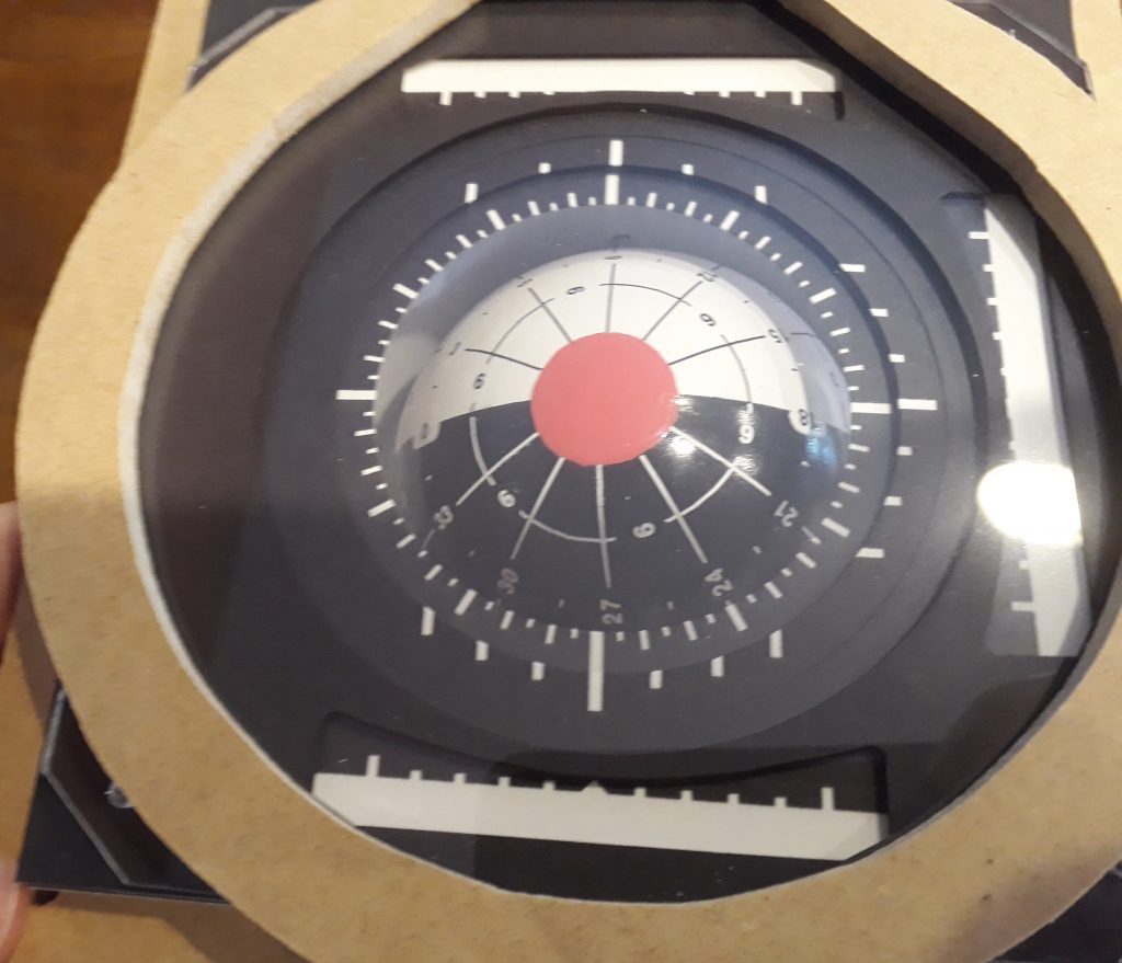
(Photo: Apollo Education Experience Project)


That FDAI looks great! I did 3 axis on mine and can provide you the parts if you want. Chinese geared motors are inside the ball to give you yaw (or is it roll?) I have a plate that the 2 halves of the dome mate to. This plate is on a gimbal with a slip ring. The assembly is on a yoke, the yoke turns by another chinese motor. This way I have x,y,z with AB encoders, power going through the sliprings. A hall effect sensor crosses over 0 on all axis so the ball is self calibrating on powerup.
What I dont have is the software to drive the angles on the number of pulses for 360 degrees. If you can do the software I will give you an FDAI.
Yours looks great though, the paint looks good, dry transfer is a good method too. I was planning on using an egg-bot with a laser or my cnc with 4 axis to engrave it.
Just poking around your site….
Sam