
Entry Monitor System (EMS) – Part 4
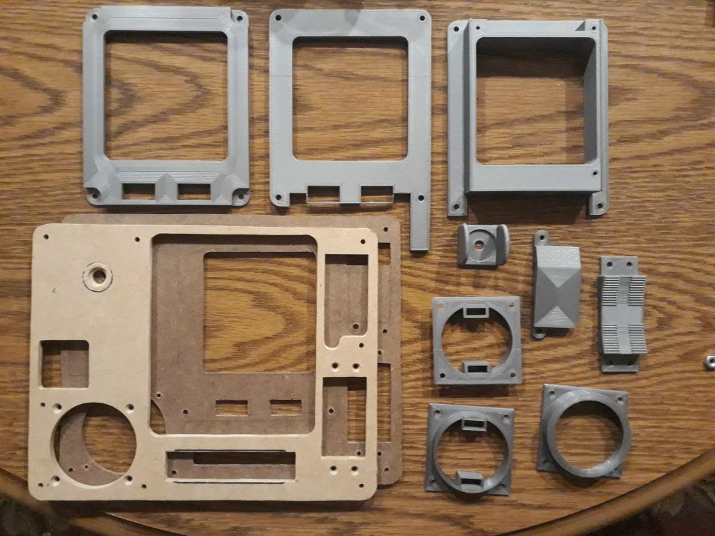
Building the faceplate for the EMS was more challenging than just a basic control panel. Not only did it have several dimensional aspects to it, I also had to mount the four circuit boards to it. Like the other control panels, this started with a base of hardboard overlayed with MDF. From that combination, I took careful measurements and modeled a number of components in Blender for 3D printing, the most significant of which were the bezel, backing plate, and housing for the graph display. This needed to be deep enough so that the amber LEDs of the graph board would be just a millimeter or two from the back of the graph, plus provide light dams around the “.05 G” and “SPS Thrust” LEDs.
Thanks to a very generous donation of a Creality CR-10S from S&T GeoTronics (www.stgeotronics.com), I was able to print these here and not have to send them off. This was particularly useful because it allowed me to quickly make changes when things didn’t fit correctly or didn’t look or work right. In addition to the graph display components, I made a bezel and inserts for the corridor indicator, a special toggle switch guard with solid sides, and non-functioning items for the GTA switch cover and the 4-way rocker switch.
(Photo: Apollo Education Experience Project)
(Photo: Apollo Education Experience Project)
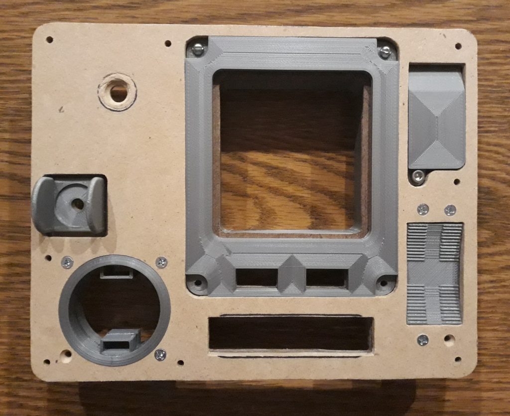
To get an idea how everything would fit together, I test-mounted all of the components for the main structure. I did have to do a bit of additional sanding (no surprise there), and I had to re-design and re-print the GTA switch cover and the 4-way rocker switch, but fortunately they printed quickly. I used the test-fit assembly to locate and drill some screw holes in the circuit boards. I already had a good idea of where they would go, so I left those areas clear of components and wires (although later on I found I needed to carve away a bit of the graph display backing to allow for a solder joint).
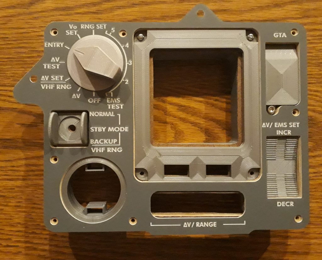
Once things started fitting well, I just had to see what it looked like with the acrylic panel overlay and switch knob, so I positioned them onto the test-fit assembly. Wow! This is going to look good! I disassembled the parts, then painted the MDF in all gray. I painted a portion of the hardboard gray as well, but I very specifically left the area around the graph display unpainted, since it would serve as-is to replicate the display’s appearance.
(Photo: Apollo Education Experience Project)
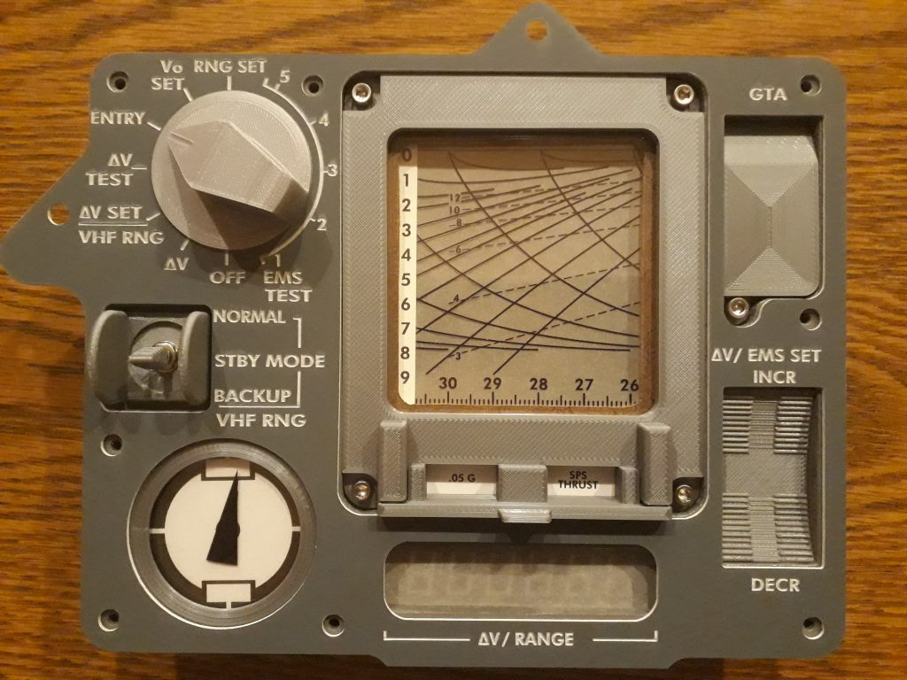
Now to create the various paper and transparency items for the graph and other displays. The counter display was the easiest – a section of transparency film backed with a section of tracing paper. I inserted these between the MDF and hardboard and taped them into place. I had already made some gauges of the same size as the corridor indicator, so I used those templates to create a needle and a face. The needle I printed on a transparency, and the face I printed on regular 20-pound paper, then cut them out to fit the bezel. I sandwiched the needle transparency between two acrylic discs and placed the paper face behind the stack, inserted the stack into the bezel, and held it all in place with one of the inserts. Then, I printed plain-paper inserts reading “.05 G” and “SPS THRUST”, cut them out, and taped them along with some transparency film to the back of the graph bezel. Incidentally, I re-modeled the bezel to include some additional detail at the bottom around these indicators.
Because the graph display wasn’t going to scroll as in the real EMS, I just chose a section from the Apollo 10 mylar scroll that looked interesting. Since that image wasn’t the highest resolution, I re-created that section, then printed it on transparency film. I created the G-force scale and printed it on the same 65-pound cardstock I used for the pages of the Open DSKY command reference. I then taped the G-force scale to some unprinted transparency film, taped the printed scroll section to that, then taped some tracing paper to that. This whole stack was then taped to the back of the hardboard. I inserted a piece of clear acrylic behind the bezel, then used cap screws to mount the bezel, backing, and housing, then assembled the rest of the pieces.
Now that the hardware is complete, I started mounting the circuit boards. The counter display was first, followed by the corridor display. I started to mount the main logic board, but found that the two cap screws for the bottom of the graph bezel were too long, so I removed them to finish installing the board and will get replacements later. Finally, I installed the graph display. The amber LEDs mounted higher on the board than I thought, and they touched the back of the graph before the board met the housing. I put some spacers in to compensate, but I also re-designed the housing and am printing a new version that is deeper. I mounted the switch, added the acrylic overlay, and secured the knob with a set screw. I then connected its ribbon cable and those for the corridor indicator and graph display, and the EMS was ready for testing!
(Photo: Apollo Education Experience Project)
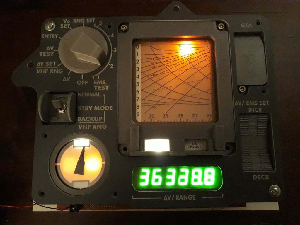
I applied power, then cycled through each of the switch positions. The EMS worked so beautifully at every step! This is going to be a tremendously interesting piece of the Command Module! I was so excited by how well it worked that I recorded a quick video showcasing its operation.
(Photo: Apollo Education Experience Project)
Although the EMS simulator can work on its own, it is designed to work in conjunction with a trigger signal from the Open DSKY. Building the interface for the Open DSKY and how it will control the EMS will be covered in a future article.


Hi Bill
Please keep up the good work. I already have donated a small amount and looking foreward to do some more.
Do you plan to publish the STL-Files for 3D-printing? I would gladly reproduce your Panels, Gauges, etc.
Daniel
Hi, Daniel,
First of all, thank you for your support of the Project!
I may release some of the STL files, such as gauges, talkbacks, etc., as-is. Others are project-specific (such as several of the EMS parts that are fit to the circuit boards) and they would need work to make them suitable for anyone to use. I have had a couple of other people asking about them as well.