
DSKY – Part 4
In order to make the Open DSKY useful for controlling other items, I needed to make an interface expansion board. I had already extended a lead from the NeoPixel chain and power from the header to operate the Caution and Warning Lights, but that existed as a pigtail and wasn’t really useful for a permanent solution.
I decided to use a small prototyping board I had lying around (older enthusiasts may recognize it as one from Radio Shack). Strangely enough, the mounting holes were nearly exactly the same spacing as two of the holes on the Open DSKY’s mounting frame, so that will be really convenient when installing this in the Command Module.
I toyed with several ideas on how to bring out the digital control lines, and finally decided on some reed relays. The Open DSKY already controls one on its circuit board, so I know it is capable of operating them. Since I had the space, I chose to install two – I knew I needed one for the EMS, and figured I would eventually need another. The Open DSKY has 3 digital lines on its header so I could have installed three, but I needed room for some other stuff.
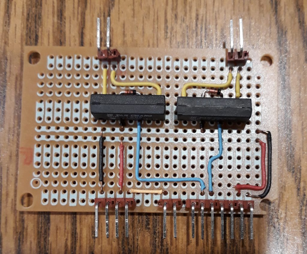
I started assembly of the board by soldering a 7-pin header that will connect via ribbon cable to the header in the Open DSKY. I wired power and ground to the two busses in the center of the board. I installed the two reed relays, put protection diodes across the coils, connected one end of each coil to ground and the other to control lines 4 and 13 (I didn’t bring out D5). I included a wire for one of the analog lines, so if I wind up needing it I’ll already have it.
I added a two-pin header to connect the NeoPixel extension. There’s only one wire now, but I may get adventurous and drill holes in the Open DSKY’s motherboard to mount a header for the NeoPixel line and ground. I also installed a four-pin header that will eventually connect to the Caution and Warning Light assembly. The finished board is small and tidy. And I still have room to add one or both analog lines if I need them.
(Photo: Apollo Education Experience Project)
I had a spare 6-pin header already wired with 5 color-coded wires, so I used it to connect to the Open DSKY’s header. I put a 7-pin connector on the other end to connect with the header on the expansion board. Because of the location of the header right under the power switch, I had to disassemble the Open DSKY to install the connector, but fortunately once installed there’s still plenty of room.
(Photo: Apollo Education Experience Project)
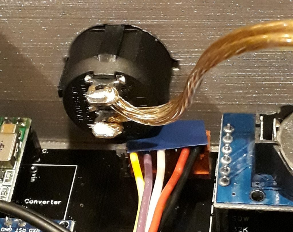
Now for the real test. I built a two-conductor ribbon cable to connect between one of the reed relays on the expansion board and a header on the Entry Monitor System (EMS) I installed for the purpose of controlling the relay in its circuitry. This relay, when activated, disconnects the activation circuitry for the re-entry and delta-V countdowns. With the new connection, the Open DSKY can run re-entry or delta-V simulations and control when entry interface occurs or when SPS ignition happens.
Since I didn’t have much memory space to do a full simulation, I added a few control commands to the “Time From Event” countdown timer routine (V16N35 / V25N35) so that the relay on Pin 4 is closed during the last minute of the countdown and reopens when the count reaches 0. How did it work? See for yourself!


