
Thumbwheels – Part 2
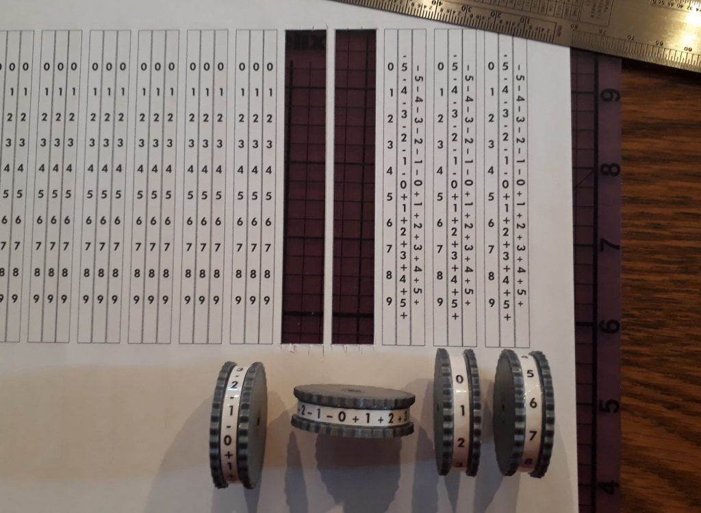
The thumbwheels that I created earlier were missing one of the most important pieces: a scale to indicate the relative level. So I measured the circumference of the wheel and the width of its center, and created a blank template of the correct size. Using the Futura font, I added a scale from 0 to 9. I also measured the amount of travel the thumbwheel made when attached to a potentiometer so that 0 would be at one end of the travel and 9 would be at the other. I positioned the 0 and 9 on the template, then positioned the rest of the numbers evenly between them.
I had a bunch of sheets of labels for videotapes left from my old video days (who uses videotapes anymore?), and thought the spine labels would make good label stock for the scales, since they were longer than most labels. I created a template in my word processor, then placed a whole bunch of completed scales on it and printed out a sheet. I used a straightedge and X-acto knife to carefully cut them out, and cut some similar-sized strips of heavy-duty clear shipping tape. The tape serves the dual purpose of holding the labels down and protecting them from wear.
(Photo: The Apollo Education Experience Project)
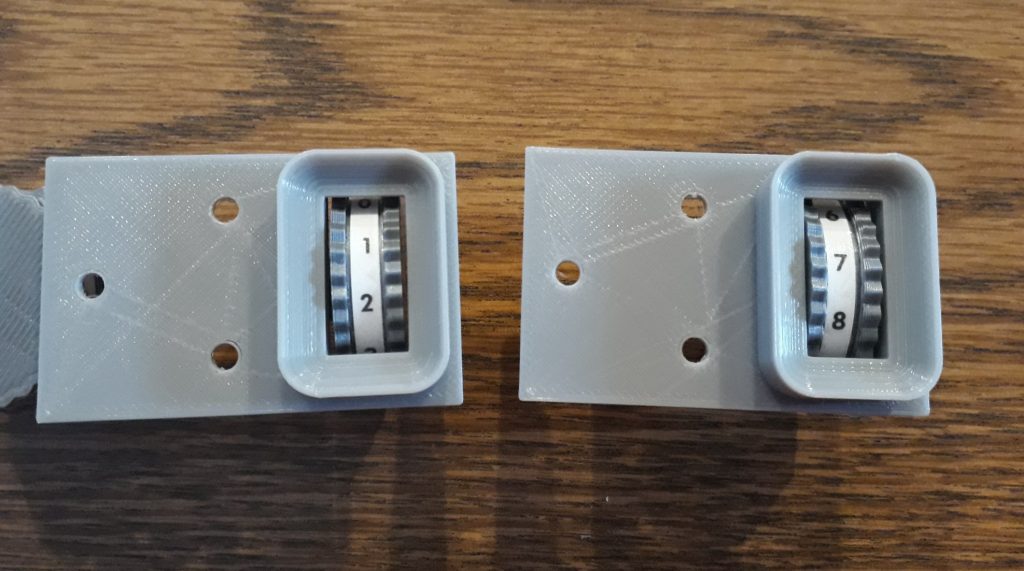
I installed a couple of newly-labeled wheels into some thumbwheel assemblies – one with a potentiometer and one dummy. I had to tweak the position on the potentiometer a bit, but got it adjusted so the scale was correct for the shaft’s rotation. The dummy didn’t have that adjustment, but it did have an unrealistic problem: the wheel could spin freely. I’m not sure at the moment what to do, but my current thought is to use an extra-long set screw which will block the travel when the set screw contacts the frame of the assembly.
(Photo: The Apollo Education Experience Project)
You may have noticed in the first picture that two of the thumbwheels didn’t have a 0-to-9 scale, but instead a scale centered on 0 with + numbers in one direction and – numbers in the other. These are intended for a particular assembly on Panel 1. This assembly has a cluster of edgewise gauges behind a single window, plus two thumbwheels for controlling pitch and yaw. Before S&T GeoTronics donated the 3D printer to the project, I had wondered how I would make that. But 3D printing made it a snap.
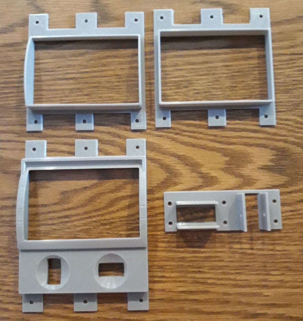
I designed it in four pieces – the main bezel, an insert for the gauge section (to hold the acrylic and gauge scales in place), a back for the gauge (to mount the lights), and a dual thumbwheel assembly – one for pitch trim and one for yaw trim. I used the model I made earlier, doubled it, and rotated one assembly 90 degrees. I added some tabs and screw holes in such a way that the gauge insert’s tabs will help secure the thumbwheel assembly in place.
(Photo: The Apollo Education Experience Project)
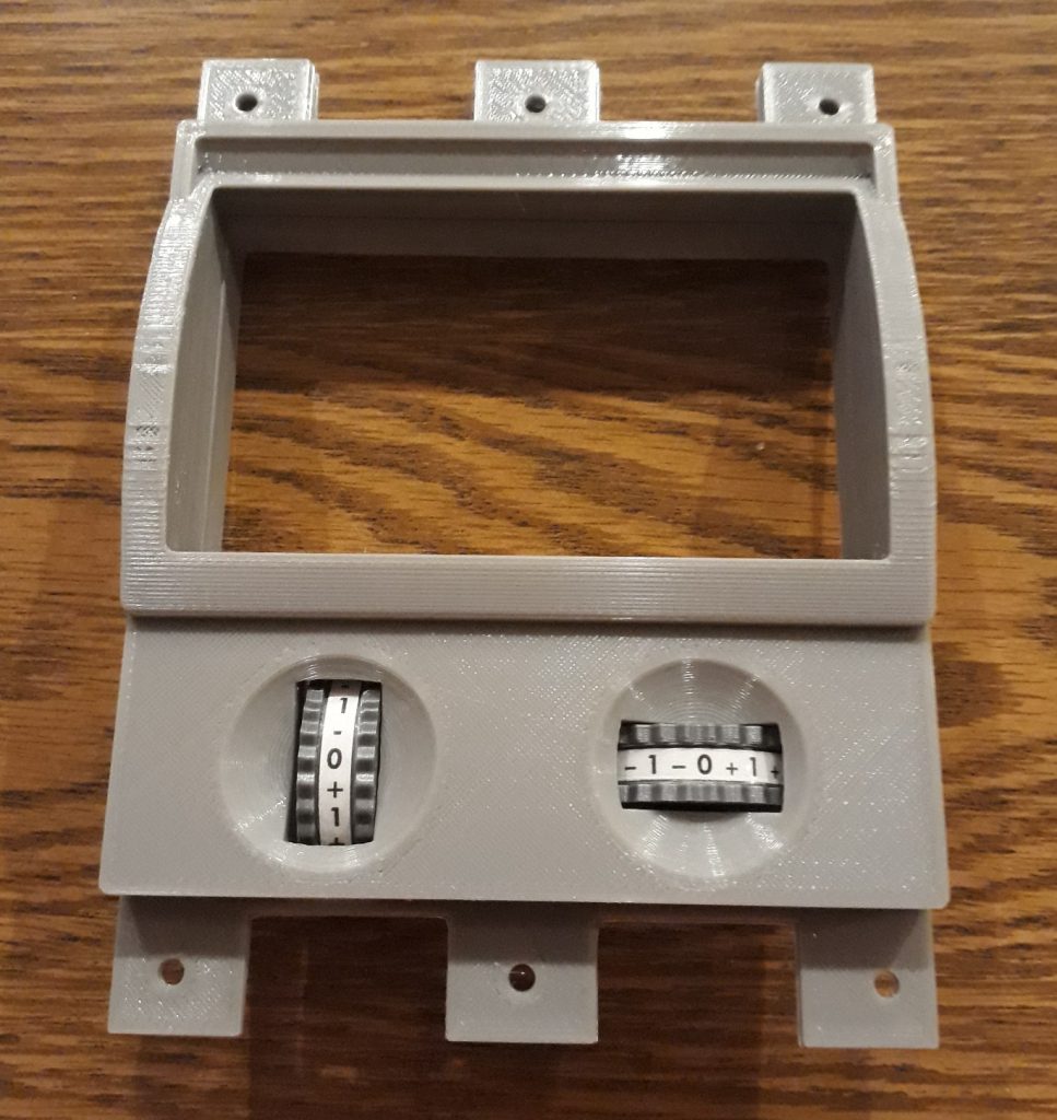
I mounted the two specially-labeled wheels in the thumbwheel assembly, then put the pieces of the whole unit together. I discovered a flaw in my model – the tabs for the gauge back interfere with the rotation of the yaw thumbwheel (the one that goes side-to-side). But the tolerance was really close, so I got the X-acto knife out again and trimmed the tabs down until they no longer interfered. Just for insurance, I trimmed the tabs of the gauge insert as well. Now the wheels can turn freely (until I install the long set screws, that is).
(Photo: The Apollo Education Experience Project)
The edgewise gauges for the upper part will be added later. I’ll post about them when I complete the other edgewise gauges.


