
Navigation Station – Part 6
Although the panel I just finished had depth to the switch recesses, they weren’t deep enough. So I traced the openings onto some 3/4″ MDF and cut those openings out to match. The one opening I did not cut was the rectangular opening for the Master Alarm switch/indicator. Instead, I marked the location for drilling a hole for it. I then matched these up with the main panel, and used a file and some sandpaper to make the sides of the recesses uniform between the layers.
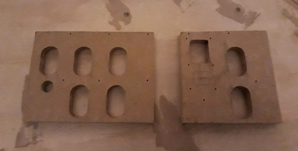
(Photo: The Apollo Education Experience Project)
After drilling a hole for the Master Alarm switch, I cut some 1/8″ hardboard for backing panels and drilled holes to mount the toggle switches centered in the recesses. I also drilled some small holes just above each of the switch pockets, and used a rotary tool to extend those holes down to the tops of each pocket. These will be used for mounting some LEDs to illuminate the switch pockets. Since these blocks will be attached to the back of the panel, the LEDs will be held in place between them.
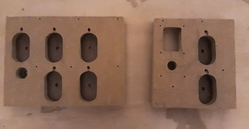
(Photo: The Apollo Education Experience Project)
I painted the backing panels granite gray, as well as the insides of the holes of the spacer blocks. When dry, I mounted the toggle switches on the backing panels. I also dug up a vintage indicator lamp to mount on the panel as the indicator for when a star is selected for navigation.
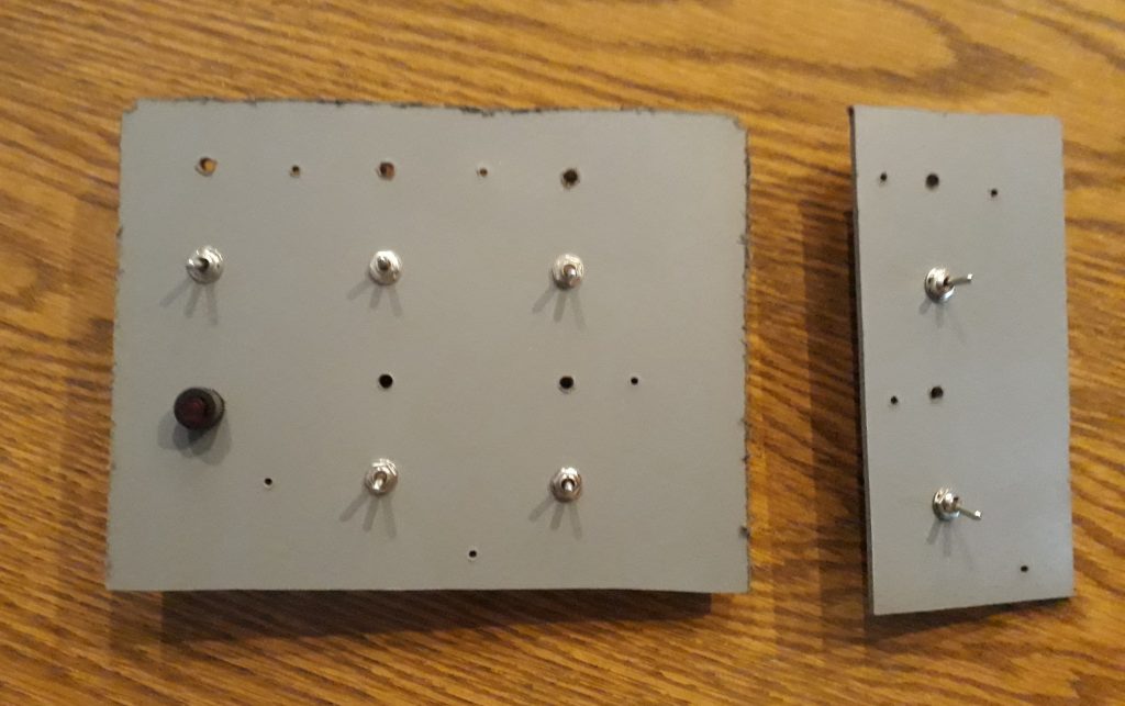
(Photo: The Apollo Education Experience Project)
I attached the completed backing panels to the painted spacer blocks. To light the switch pockets, I selected some warm white LEDs with pre-installed dropping resistors and leads. I bent the leads near the LEDs to make a 90-degree angle, then fed the leads through the holes. The LEDs came to rest in the grooves cut with the rotary tool very nicely, with the tops pointing down toward the switches. I drilled a pair of holes in each assembly, inserted some machine screws, then attached the leads from the LEDs to them with nuts and washers – one for the anodes and one for the cathodes. I’ll attach power from a dimming circuit to these later.
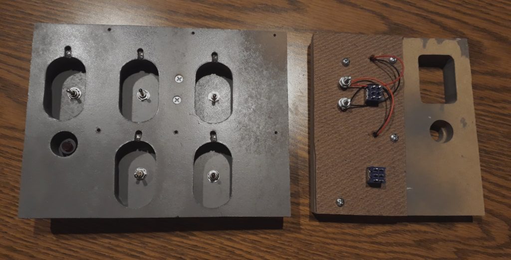
(Photo: The Apollo Education Experience Project)


