
Navigation Station – Part 7
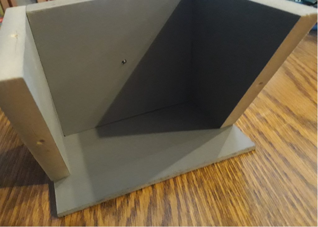
The next difficulty with the navigation station was the control pockets. On the real CM, these don’t have corners but rather rounded edges and appear to be molded out of a single piece of material. I chose instead to make the pockets using good ol’ MDF and hardboard. I considered modeling these and printing them with the 3D printer, but there were just so many issues with printing something like this that I decided against it.
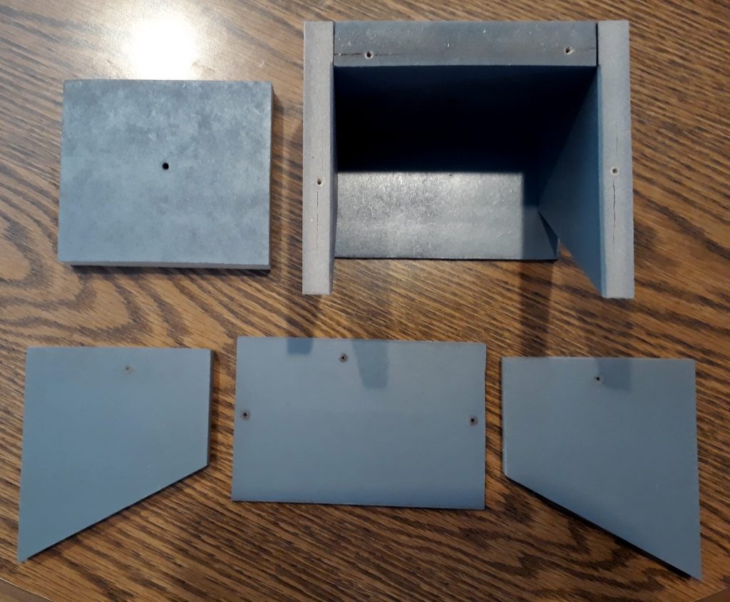
I had two dimensions for the pockets – width and height – but I didn’t have a dimension for depth. Referring to a number of different photos and drawings, I came up with what appeared to be a reasonable “guess-timate” for the depth. From these dimensions, I came up with a design for the pockets using 5 pieces of material. I cut, assembled, test-fit, disassembled, and painted the 5 pieces for each pocket, then reassembled 4 of them. The 5th piece for each pocket will have controls mounted on them before being fastened to these assemblies.
(Photo: The Apollo Education Experience Project)
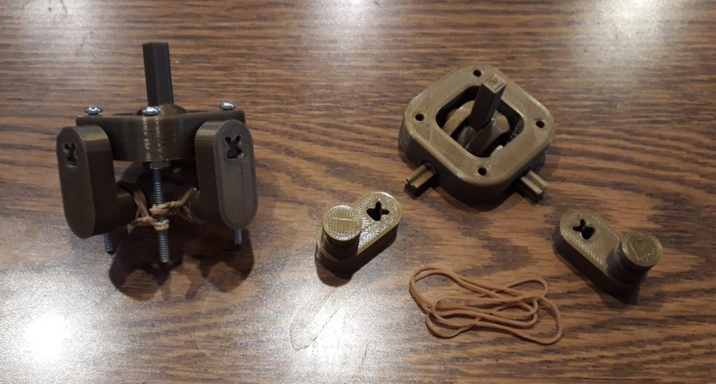
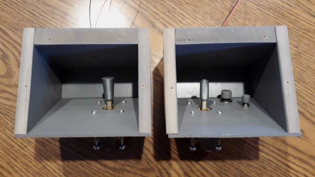
In each pocket is a small joystick – one for making fine position adjustments of the CM, and one for manipulating the sextant. Rather than trying to find real joysticks of the correct size, I found a 3D model on Thingiverse for a “print-in-place” joystick gimbal assembly (https://www.thingiverse.com/thing:2156713). I resized and modified the model slightly to prevent stray movement of the stick up and down in the gimbal, and to add some arms to the axes for attaching rubber bands to auto-center the joysticks.
(Photo: The Apollo Education Experience Project)
Strangely enough, the two joysticks have two different handles. I actually don’t know the reason for that, but there’s probably a good one, whatever it is. But I needed to replicate them. So I modeled them and 3D-printed them, with an opening in the base sized to fit snugly onto the shaft of the joystick gimbal. Even though it was a friction fit, I still added a drop of superglue to prevent accidental removal.
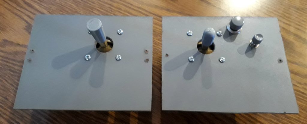
I also came up with a pair of momentary switches that approximated the sizes of those in the real CM, and painted their caps granite gray. Once dry, I installed them along with the joysticks into the 5th panels for the pockets.
(Photo: The Apollo Education Experience Project)
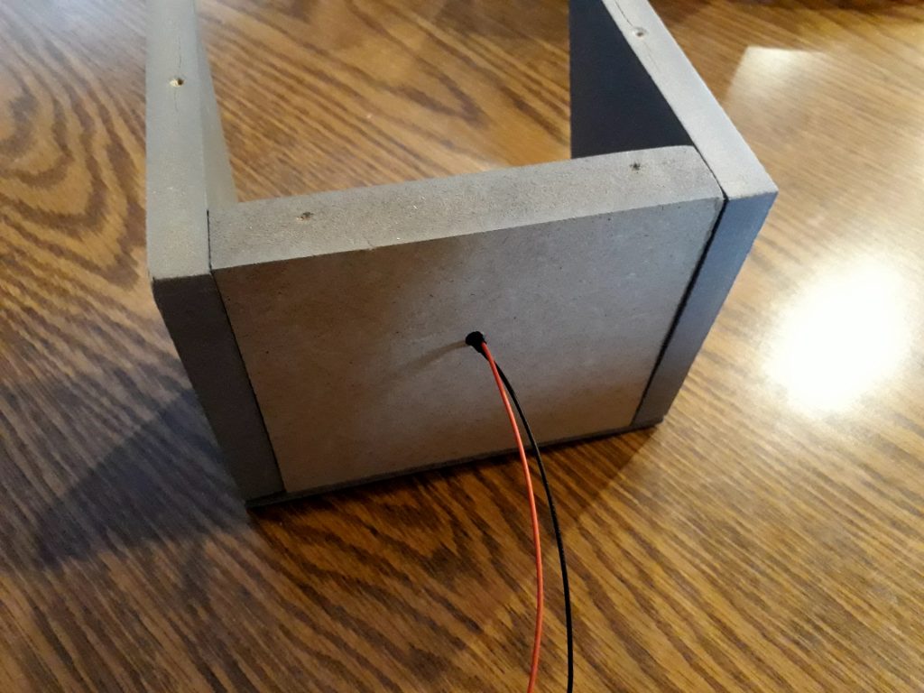
Like the switch recesses, the control pockets are supposed to be lighted. I could not sandwich LED between layers like I did with the switches, so I drilled holes in the tops of the pockets for them. I drilled them at an angle so that the tops of the LEDs would point directly at the controls. I also drilled them in two steps: first, I drilled holes just big enough for the domes of the LEDs, then I enlarged the holes not quite all the way through the material so that when inserted, the LED would protrude from the surface but not fall all the way through.
(Photo: The Apollo Education Experience Project)
(Photo: The Apollo Education Experience Project)
Finally, I attached the completed control panels to the pocket assemblies.
(Photo: The Apollo Education Experience Project)


