
CM Interior – Part 8
I’m about to shift the focus of construction onto the main control panels, but I want to get to a clean stopping place before I do. There’s a reason for this, which I will announce at a later time. Also, I apologize for the delay in getting this posted – a lot has been going on behind the scenes and has kept me from updating the site (although work is definitely progressing).
There are two more doors similar to R6, which I installed earlier – R5 and L2. Both of these have oddly-shaped frames and doors because they fit against the wall of the CM. I started with R5 in the Right-Hand Equipment Bay (RHEB) by using a bendable ruler to get the correct curve for the top edge, then cut the frame from 1/2″ MDF. I had already installed some braces, so after painting the frame I installed it onto the braces.
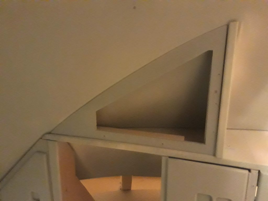
(Photo: The Apollo Education Experience Project)
I then cut the door and assembled it similar to other doors I’ve already completed. After painting it the same Serenity Blue, I installed it using the pre-painted screws.
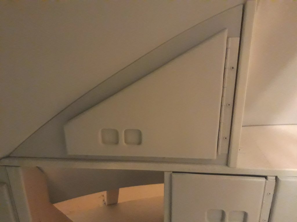
(Photo: The Apollo Education Experience Project)
I repeated this process for the frame and door for compartment L2 in the Left-Hand Equipment Bay (LHEB) on the opposite side of the CM.
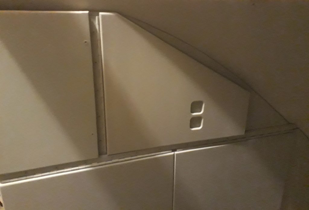
(Photo: The Apollo Education Experience Project)
The next door I tackled was B1 in the Lower Equipment Bay (LEB). This is another of the lockers where food was stored for the Apollo missions. I didn’t have a frame to cut since it was already framed by structural items, but it did have a special need – a sliding bracket. The door for B1 actually did have a sliding bracket similar to the one I’m installing. But first, I cut, assembled, and painted the door, then carefully installed it. “Carefully” is important, because without the sliding bracket, it could easily fall open and break something (this is not in zero-G). Once it was installed, I taped it shut with blue painter’s tape to keep it from falling open.
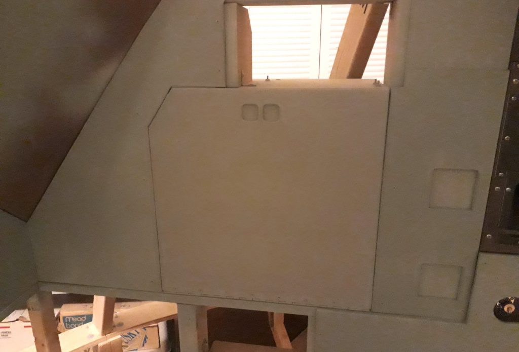
(Photo: The Apollo Education Experience Project)
When I was ready to install the bracket, I opened the door to the fullest open position I wanted (so that it would not damage the panels below it), positioned the fully-open bracket where it needed to fit to allow operation of the door, and marked the positions for the screws. I mounted it first on the fixed position, then installed the screws into the door itself. I tested operation to ensure that the slide didn’t bind, and it worked great!
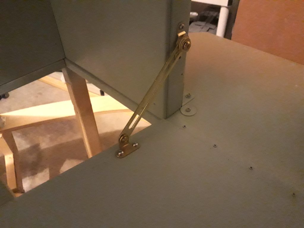
(Photo: The Apollo Education Experience Project)
Below compartment B1, I needed to install another closeout panel and 3 doors. The doors made for a very complicated shape for the panel, so I took several measurements, made several drawings, and checked everything before taking the jigsaw to the 1/4″ MDF. I installed the panel to get the mounting screw holes pre-drilled, but took it back out for painting and because installation of the doors needed be coordinated with its installation.
The first door was for compartment B3. Although originally intended for stowage of several small items, this will serve in the replica to provide access to an unannounced addition to the CM. Unlike all of the doors installed so far, this one is painted metallic silver to match that on the real CM. A portion of its hinge is under the closeout panel, which is why the two needed to be installed together.
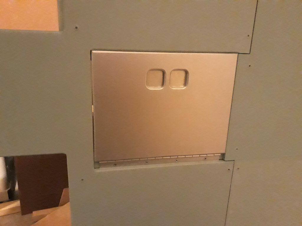
(Photo: The Apollo Education Experience Project)
I assembled and painted two more doors – B2 (Serenity Blue) and B8 (metallic silver). These were installed onto the same closeout panel as B3, but with their hinges on the outside.
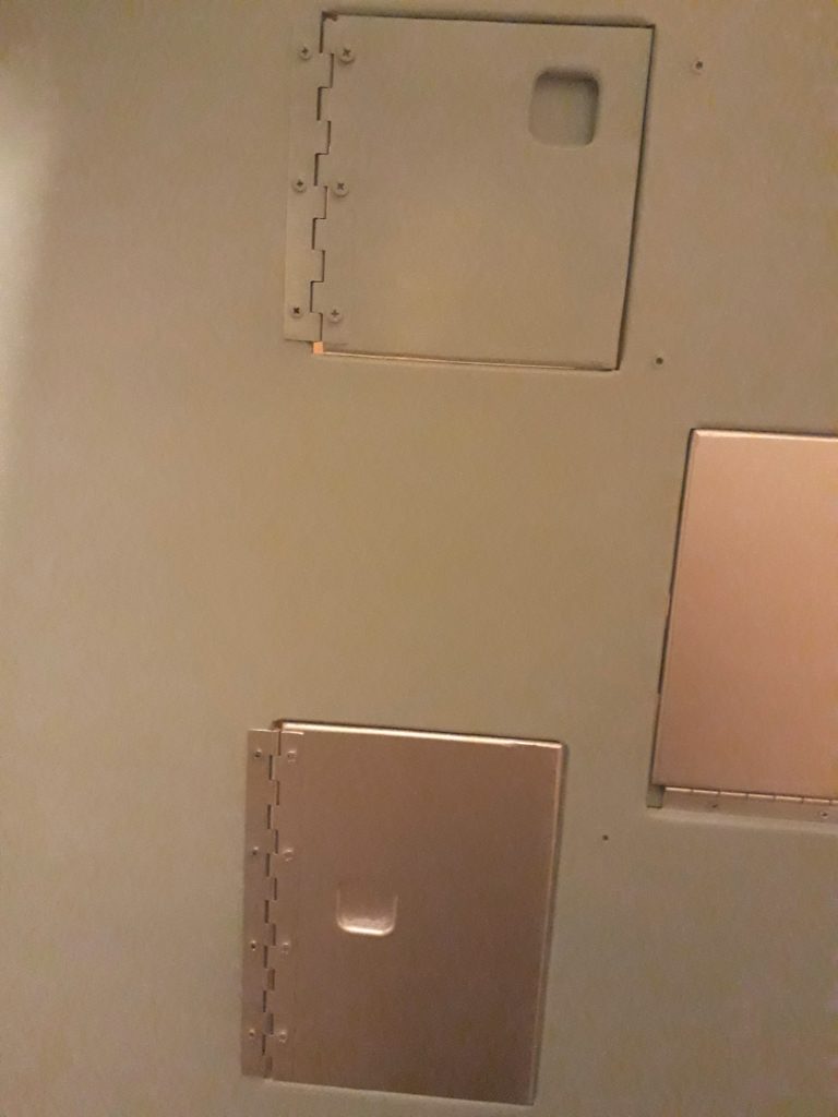
(Photo: The Apollo Education Experience Project)
I needed one final closeout panel to complete the non-functional portions of the LEB. It would fill the gap beneath the closeout panel under the navigation station down to the floor. Although the shape was not nearly as complicated as the previous panel, getting it to fit against the faceted floor was a little tricky. But once it was cut and painted, it went in smoothly.
(Photo: The Apollo Education Experience Project)
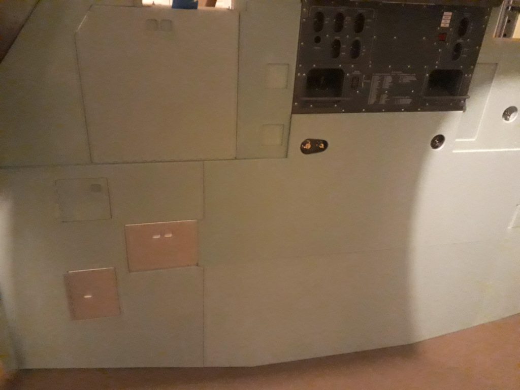
Even though there is still a fair amount of work to do on the bay half, a great deal of progress has been made. Compare this photo with the similar photo of the structural framework seen in an earlier article, and you’ll see how far it has come!
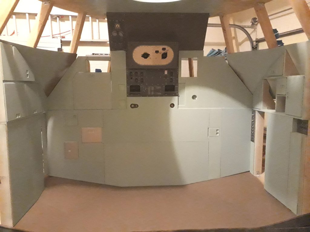
(Photo: The Apollo Education Experience Project)


