
Navigation Station – Part 3
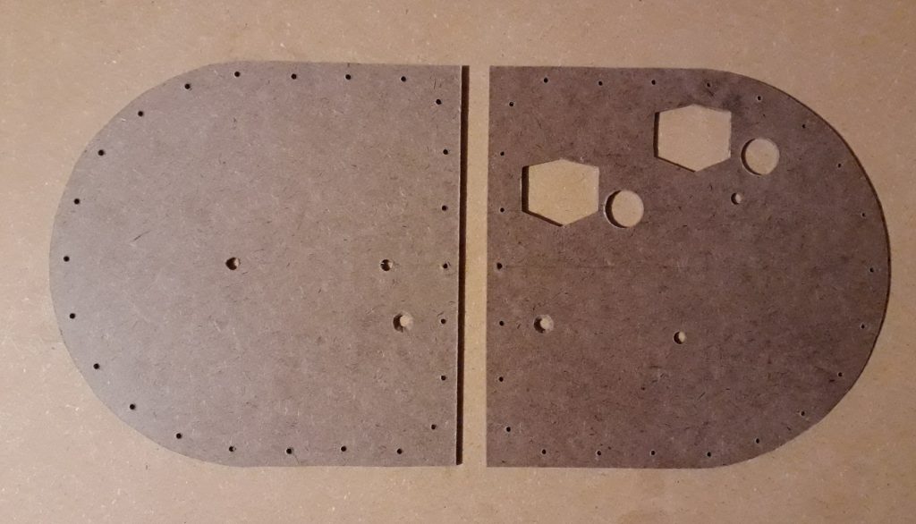
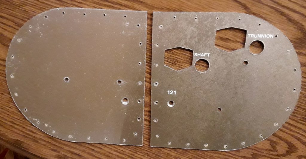
I took the two hardboard faceplates for the sextant and telescope and marked the positions of the various items and attachment screws from a full-size template. I cut the hexagonal openings for the mechanical displays first, since the material would be the strongest for the jigsaw without any of the drilled holes. I test fit the bezels, and they were tight, so I filed out the openings a bit. Then I drilled holes for all the remaining components.
(Photo: The Apollo Education Experience Project)
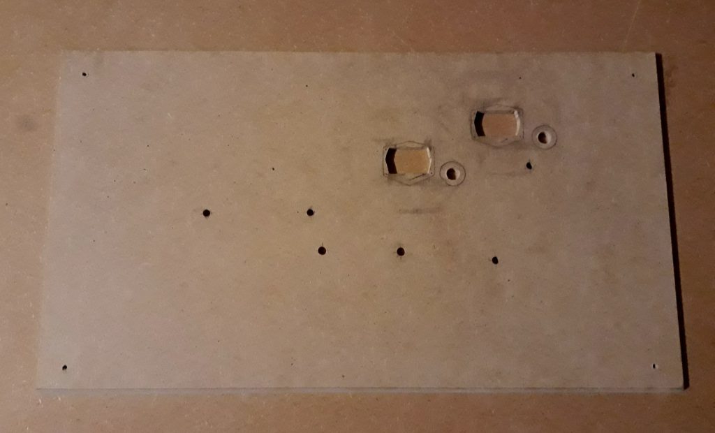
I positioned these freshly-finished faceplates onto the assembled housing so I could mark the drill/cut locations on the MDF so that they would match. I removed the faceplate from the housing, then cut and drilled the MDF. Some of the holes are a different size or shape depending on which components will be installed, particularly the mechanical displays.
(Photo: The Apollo Education Experience Project)
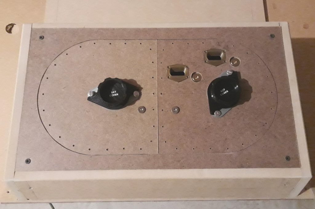
I reinstalled the faceplates onto the housing. I dry-fit the rounded faceplates and all of the various components to ensure they would fit and are in the correct locations (and that they looked good). Again, a little filing/sanding was needed for a nice clean fit.
(Photo: The Apollo Education Experience Project)
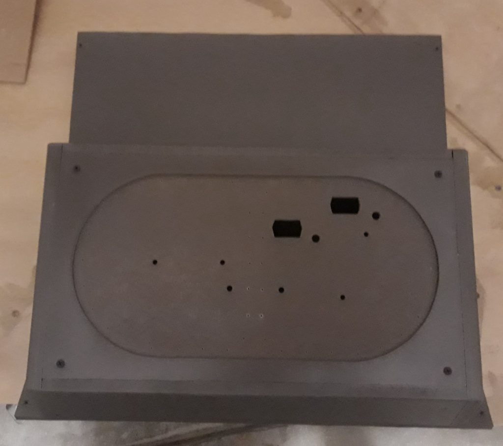
I removed the components and the rounded faceplates, then sprayed the housing assembly granite gray. Edges of the 1/2″ MDF face forward, but they have a hard time accepting the paint, even with it having its own primer. I had to hit it several times to get the paint to finish correctly.
(Photo: The Apollo Education Experience Project)
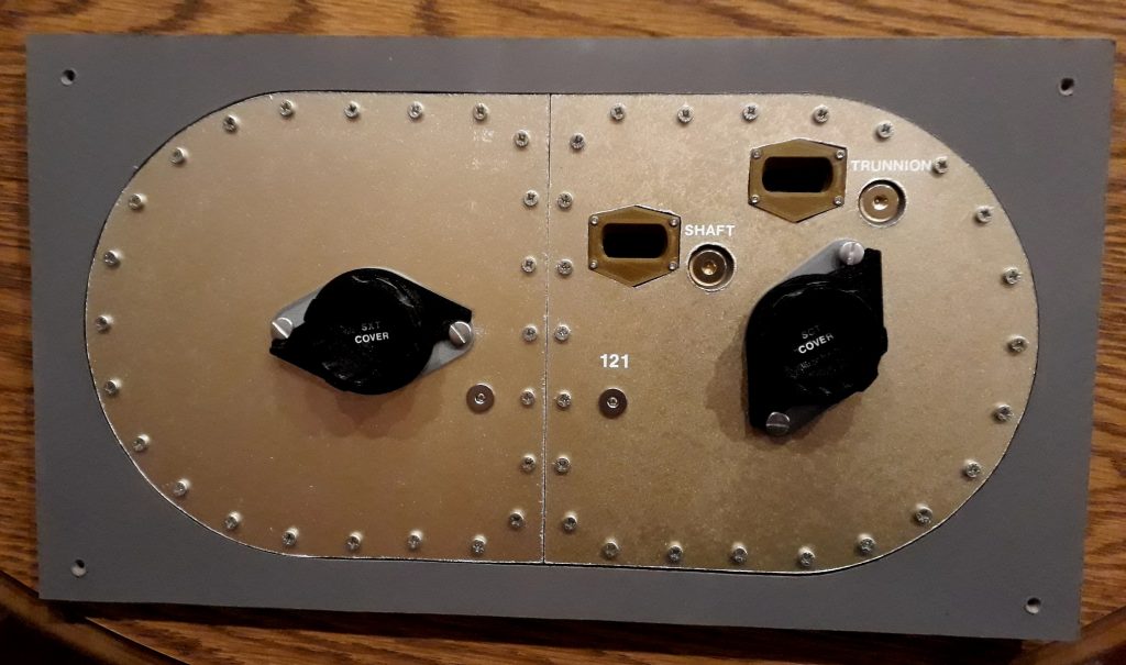
I primed the two rounded faceplates, then painted them with “gilded brass”. Unfortunately, the paint did not work correctly, and came out silver instead of “gilded brass”. It also left a weird texture, although after letting it dry for a couple days the texture flattened out. Before cutting new panels, I tried the paint again with a second coat, and this time it came out “gilded brass” and didn’t leave nearly the same texture as the first coat. Once that coat had dried for a couple of days, I added the panel number (“121”) and labels for “Shaft” and “Trunnion” using dry-transfer lettering. A coat of glossy clear to seal both the letters and the paint, and the faceplates were done.
(Photo: The Apollo Education Experience Project)
I removed the full faceplate from the housing one last time to pre-drill the 48 screw holes and to mount everything. The adjustments for the shaft and trunnion are 1/2″ brass hex-socket connection bolts, which look virtually identical to the actual adjustments on the real CM, saving me from having to make them from scratch.
(Photo: The Apollo Education Experience Project)
The final detail I added was a 7/16″ gray “D” profile weatherstrip around the faceplate. This was “peel-and-stick”, so it was easy to install. It doesn’t actually seal anything here, just looks like it does. I reinstalled the entire sextant/telescope assembly into the CM. Looks fabulous!
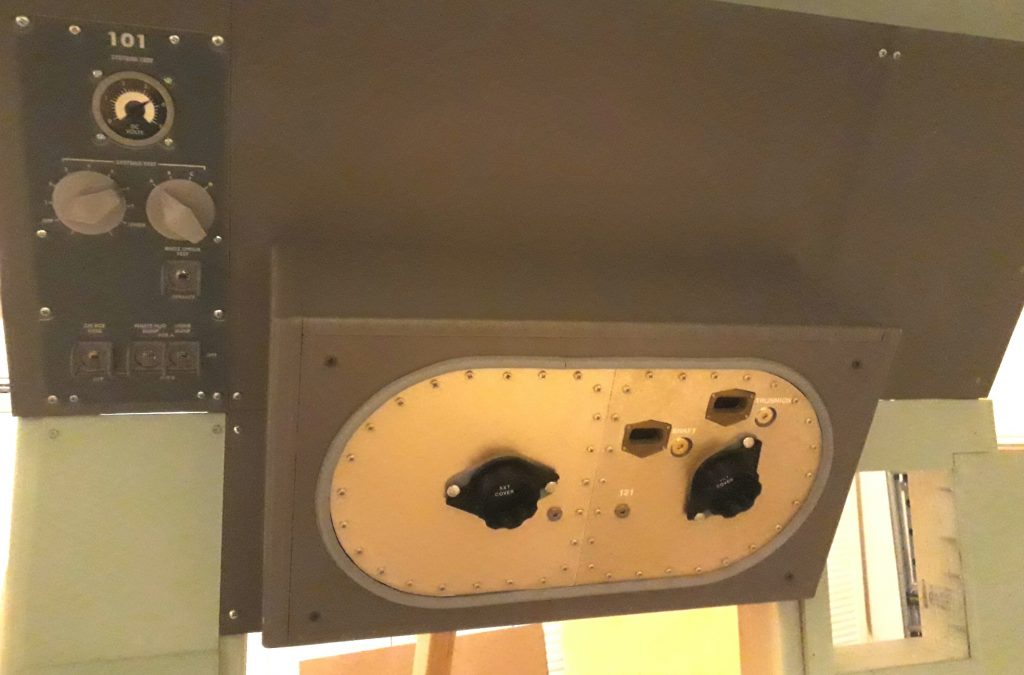
The stowage for the eyepieces has yet to be made at this point.
(Photo: The Apollo Education Experience Project)


