
FDAI (or “8-Ball”)
One of the things I knew going into this project was that I would need to make a decent replica of the Flight Director Attitude Indicator, or FDAI, commonly known to the Apollo astronauts as the “8-ball.” This was a mechanism similar to the artificial horizon of normal aircraft, but with a full three degrees of freedom to rotate 360 degrees in roll, pitch, and yaw. Scouring the Internet for sources, I saw several homebuilt projects trying to create a working replica for NASSP or Kerbal or something. It was apparent that a fully-functional replica was out of the question for me, since the Project’s CM wasn’t intended to be a fully-functional simulator. I decided to simplify it from a functional standpoint, but wanted to make the appearance as realistic as possible.
I started with some 3.5″ diameter MDF balls ordered from Amazon. I very carefully and precisely measured the diameter, and created a paper measuring tape marked in 5-degree increments for use in marking the balls. The first task was to mark the “poles” (pivot points) for the first degree of freedom, which would correspond to yaw, followed by marking the “equator” for painting the two halves white and black. I suspended the balls on some wire thru the poles, sprayed one half white, masked at the equator, and sprayed the other half black.
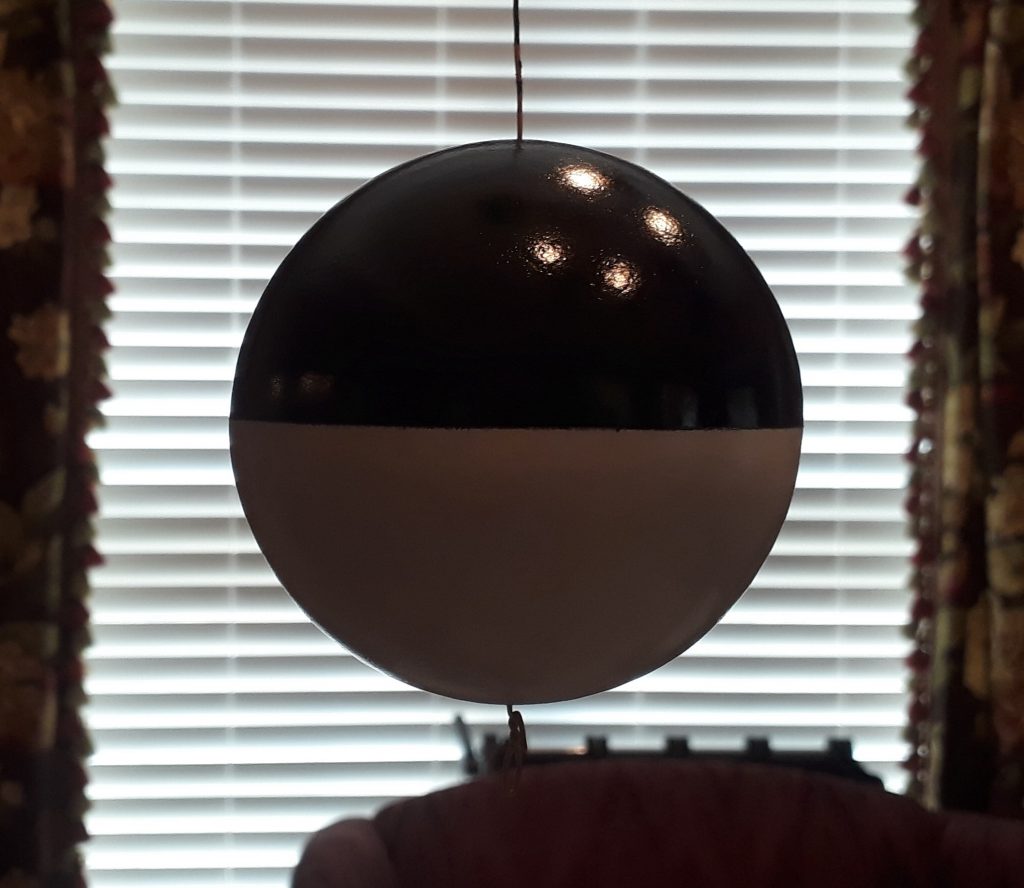
(Photo: Apollo Education Experience Project)
Once the paint dried, I removed the wire and mounted the ball in a makeshift “yoke.” I made the yoke from a PVC reducing adapter – I drew a line 1/2″ back from the 4″ end, marked one spot on the line and carefully measured halfway around to make a second mark. I drilled holes at these marks just large enough so a screw could freely turn, then using wood screws mounted the ball in the yoke. The ball could now rotate freely in one direction. This would come in handy for further painting and marking.
I marked the equator in 5-degree increments using the paper tape. I identified eight locations along the equator where the 0 degree and 180 degree pitch markings would be, and used a white paint pen to create “dimples” into the black to allow the numbers to be right on the line instead of off vertically.
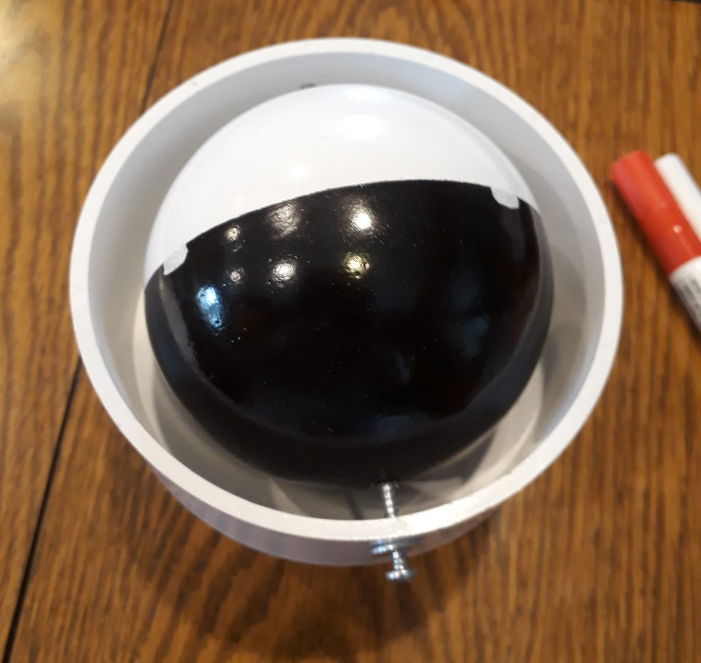
(Photo: Apollo Education Experience Project)
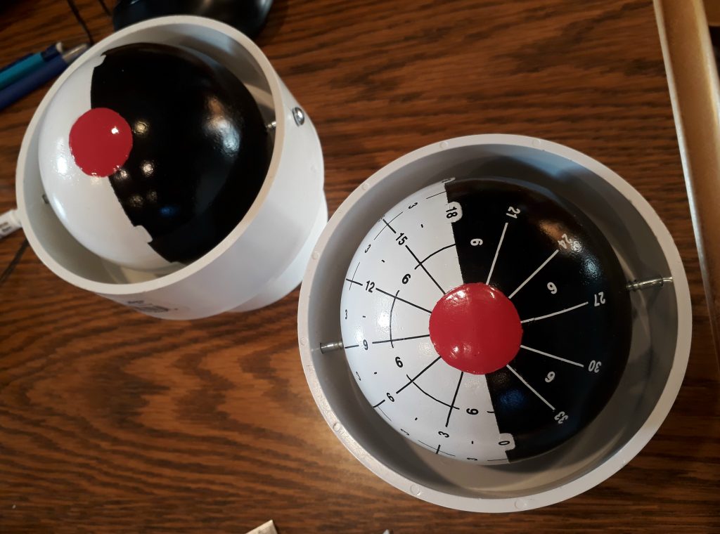
At the 90-degree and 270-degree positions along the equator, I marked off 15-degree radius (30-degree diameter) circles. Using a red paint pen, I colored in these circles to create the two “gimbal-lock” zones.

(Photo: Apollo Education Experience Project)
Next, I marked of a series of circles 15 degrees apart representing pitch, followed by marking those circles in 15-degree increments from gimbal zone to gimbal zone. Using these markings, I started applying dry-transfer decals for the numbers and lines – black decals on the white hemisphere and white decals on the black hemisphere. The 0-degree and 180-degree numbers for pitch fit into the white “dimples” painted earlier.
(Photo: Apollo Education Experience Project)
Needless to say, this was a time-consuming process, but the end result was well worth the time and effort.
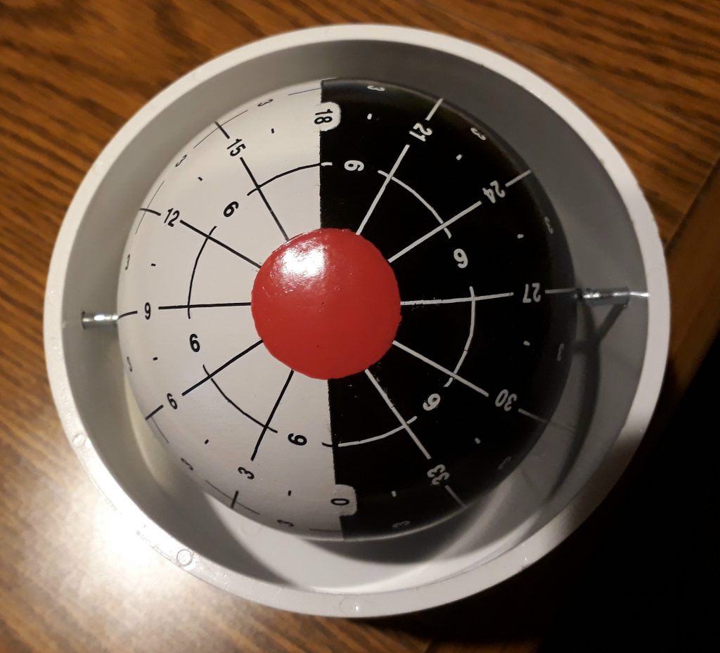
(Photo: Apollo Education Experience Project)


