
CM Framework Construction – Part 3
I mentioned in the previous framework construction article about my inability to find a CNC and calling on the Johns Creek Staples Print Department to print full-size cutting templates. The parts I needed this most for were the segments for the circular “girdle” around the base of the Command Module. Not only are they large, but they’re also curved and have a bevel. So to make the template, I arranged the pieces from the computer model so that they would fit into a 4′ x 8′ area, then enlarged that to actual size. Not having paper that wide, they printed it on two sheets that were 3′ wide and I taped them together.
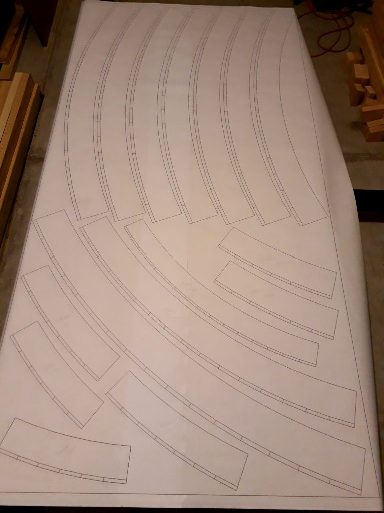
(Photo: Apollo Education Experience Project)
Notice the double lines on the outside edges of the pieces. These represent the bevels needed. When I transferred the templates to the plywood, I transferred only the inside line so I could use it as the cutting line and have the jigsaw set to the correct bevel. In addition to the “girdle” segments, I also included patterns for the window and hatch frame pieces. Some of these are very similar in size, so I made sure to label them.
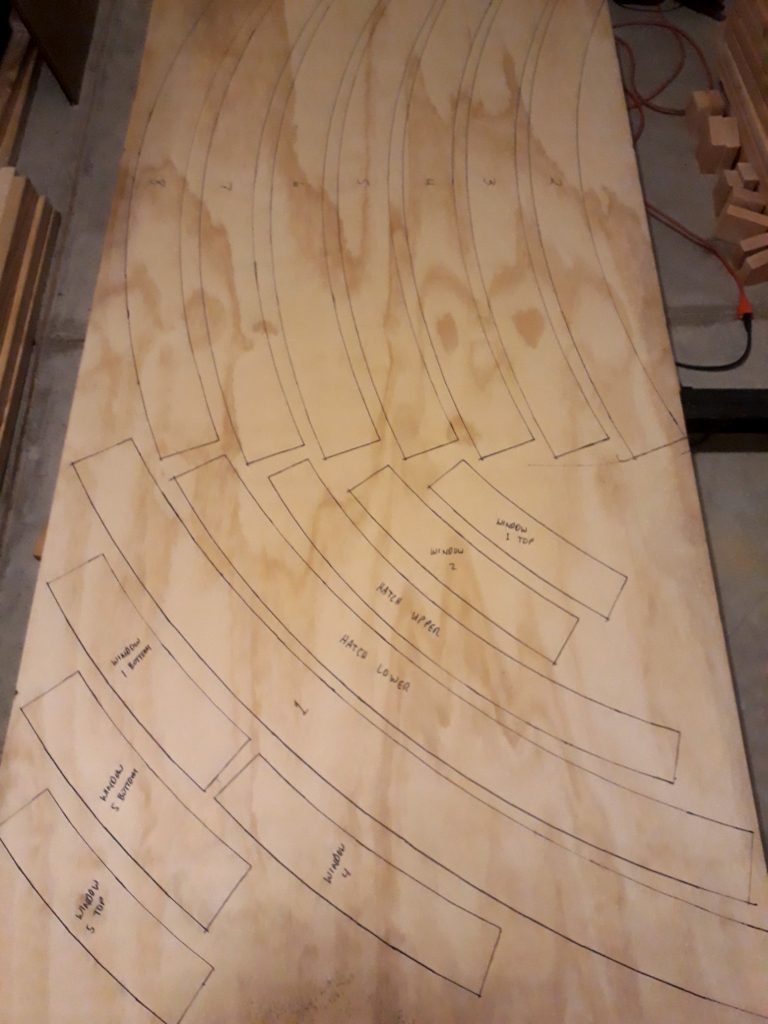
(Photo: Apollo Education Experience Project)
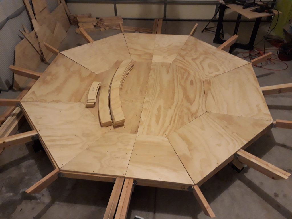
With the patterns transferred, I took the plywood to my shop where I could clamp it to a work table for cutting so it doesn’t move around. I set the jigsaw to an angle of 58 degrees, then started cutting. 3/4″ plywood is tough to cut with a jigsaw, and especially at a 58 degree angle! My venerable 25-year-old jigsaw bit the (saw)dust, so I got a new variable-speed jigsaw with work light from the Brookwood Home Depot. This thing put my old jigsaw to shame! It cut through the plywood like a hot knife through styrofoam! After a bunch of cutting, I finally had all the curved pieces with 58-degree bevels. CNC? We don’t need no steenkin’ CNC!
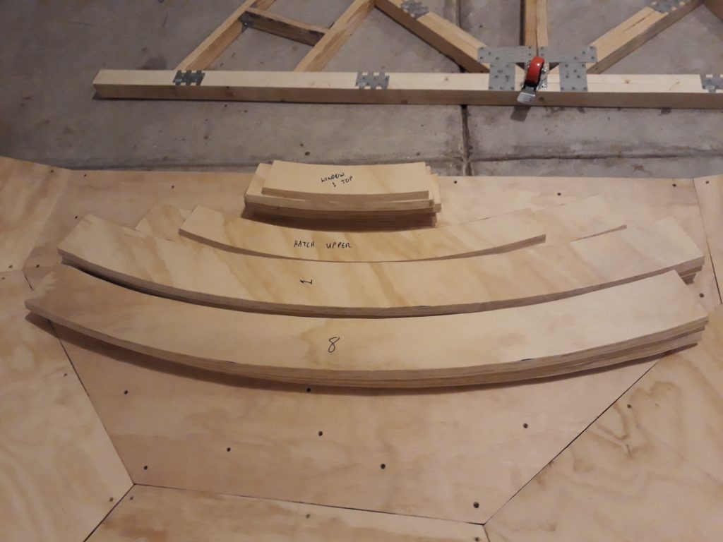
(Photo: Apollo Education Experience Project)
As the photo above shows, I had started work on the other half of the base. Except for some additional support beneath the floor for the crew couches on the hatch half, the other half is virtually identical. Construction went much faster, having done it all before.
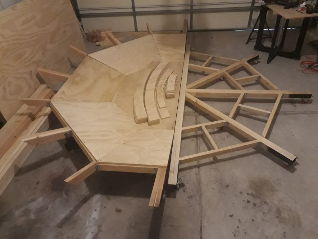
(Photo: Apollo Education Experience Project)
(Photo: Apollo Education Experience Project)
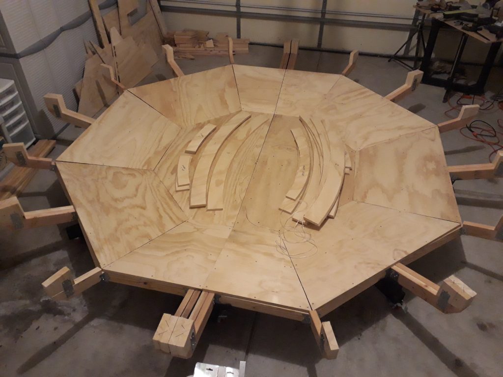
Once both halves had their flooring installed, I cut a bunch of 2″x6″ segments to mount on the tips of the radial arms. These tips will support the “girdle”, which will in turn both support the upper conical structure and provide a curved form for the outer skin of the CM. This was much harder than it appears. I got a laser level to help with the task, only to find that not only is my garage floor not level, it’s also not even. I literally had to map out the floor’s elevation contour, then measure the height of each radial arm (my construction wasn’t precise enough to make them all the exact same height). I also measured the distance from the center of the bases to the ends of the radial arms, and marked the farthest point common to all of them (no, they weren’t exactly equal, either). Because of the angle and the variable heights, I had to do some math to determine the heights of each tip so that the girdle will be level all the way around. I also had to number them since each piece fit a specific arm.
(Photo: Apollo Education Experience Project)
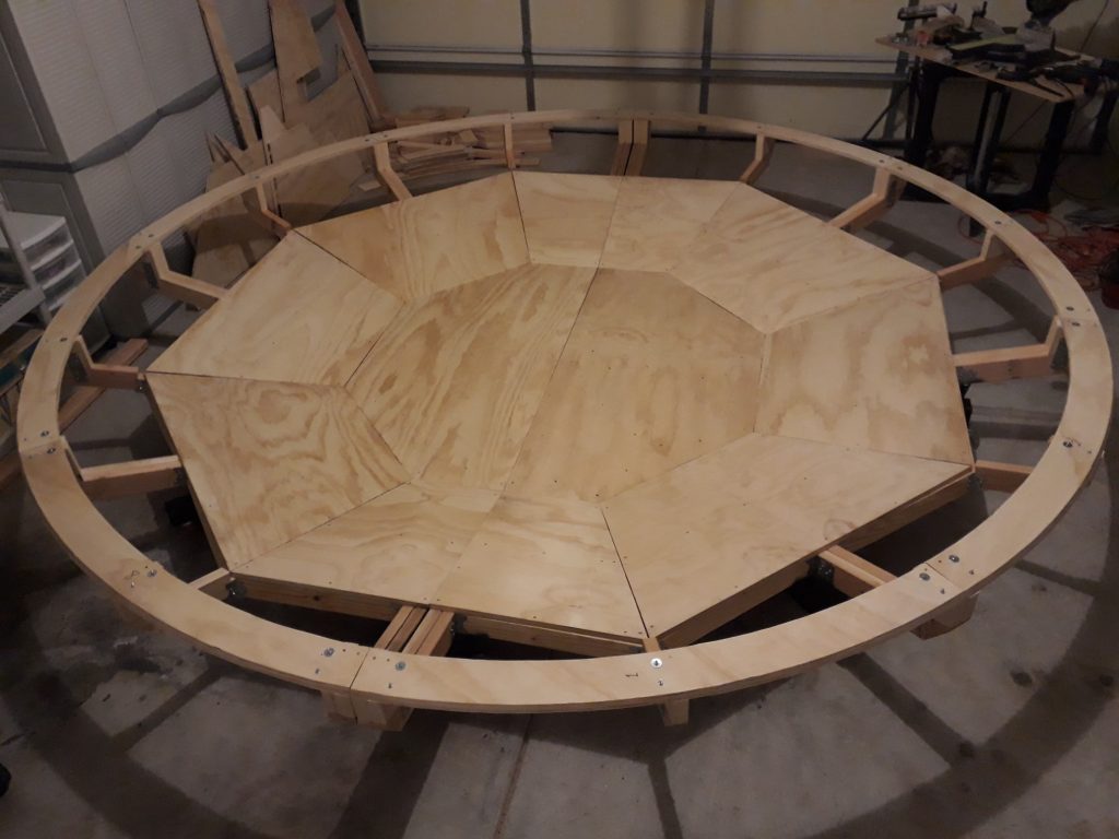
Finally came time to install the “girdle” or circumference of the base. I positioned the 8 segments on the support tips to test fit. To my astonishment, all four of the segments for the hatch half fit exactly! I wasn’t so lucky with the other half. I mounted the four hatch half segments and three of the other half segments with steel brackets, then measured how much I needed to remove from the eighth segment. Turns out only about 1/2″ needed to be taken off of one end. Considering that the circumference is nearly 40 feet, that’s not bad considering all the pieces were cut by hand … MY hand at that!
(Photo: Apollo Education Experience Project)
At last! Time to start on the cabin structure!!


