
Navigation Station
The most prominent portion of the Lower Equipment Bay (LEB) is the Navigation Station, where the astronauts could perform celestial navigation to realign the Inertial Monitor Unit (IMU) or navigate in the case of a system failure. And the most prominent portion of the Navigation Station is the sextant/telescope assembly. I’m certainly not going to provide a functional sextant and telescope, but I do still need to recreate the appearance of them.
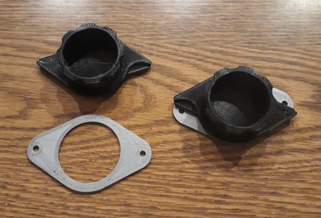
The sextant and telescope have removable eyepieces that are stored in a compartment when not in use (they project into the cabin and could get broken during launch or if knocked accidentally). When the eyepieces aren’t attached, covers are placed over the openings. I modeled the covers in two pieces: bases that I 3D-printed in silver, and covers that I 3D-printed in black. The cover for the telescope is a mirror-image of the one for the sextant, so I made sure to do this. Both covers have a ring that snap-fits into the bases, which would then be secured with binding post screws.
(Photo: The Apollo Education Experience Project)
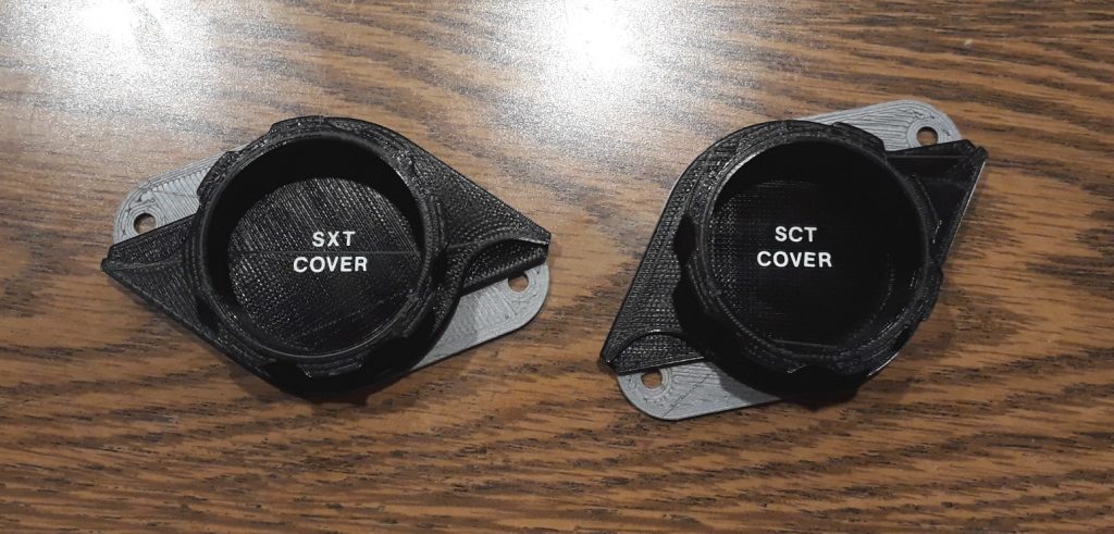
To identify which cover is which, I used dry-transfer lettering to add the labels. This was a bit difficult, since the labeled area was recessed quite a ways. I used a hobby knife to remove the letters one at a time, applied them, and burnished them. Once the lettering was complete, I sprayed both with a coat of clear paint.
(Photo: The Apollo Education Experience Project)
The scanning telescope has two positioning controls: the “shaft” and the “trunnion” – basically, the two axes for adjusting the position of the telescope. Each control also has a mechanical digital display showing the angle in tenths of a degree and finer hash marks on the tenths. This display operates like a car’s odometer – small wheels with the numbers going around the edge. Again, I’m not planning on making this functional, but it needed to look relatively correct. I modeled a frame that would hold three wheels to the left of the decimal point and one to the right, and the wheels to mount in the frame. A screw would hold the wheels in place.
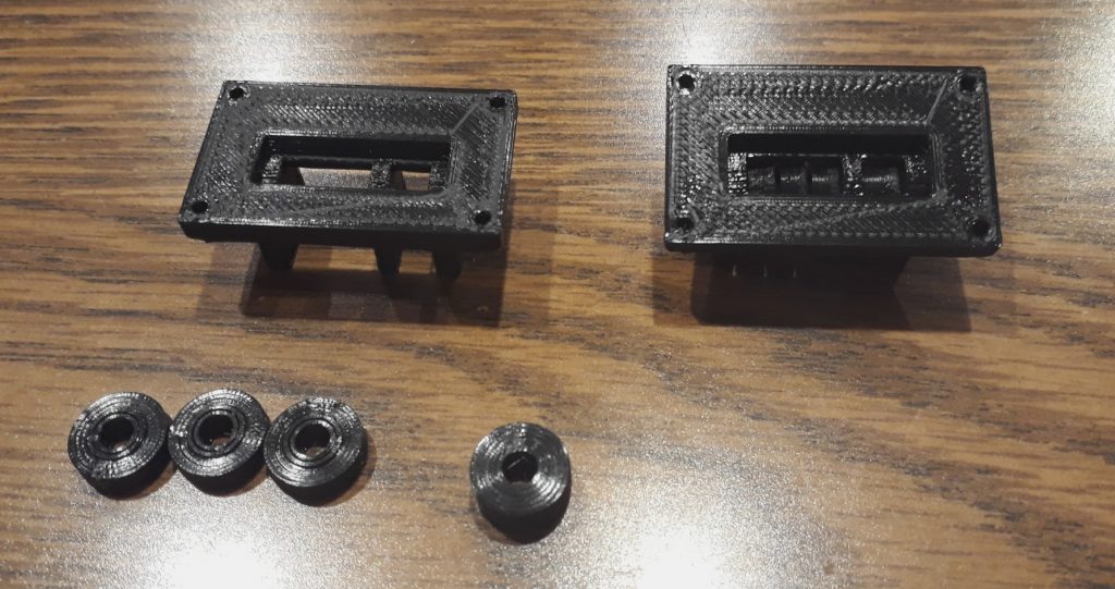
Individual components on the left, test-fit assembly on the right.
(Photo: The Apollo Education Experience Project)
The next piece would be the bezels for the mechanical displays. I designed these so that they would fit into a hole from the front and the frame assembly with the digits would fasten from the back. They would be mounted with tiny #2-56 hex socket cap screws. I printed them in gold.
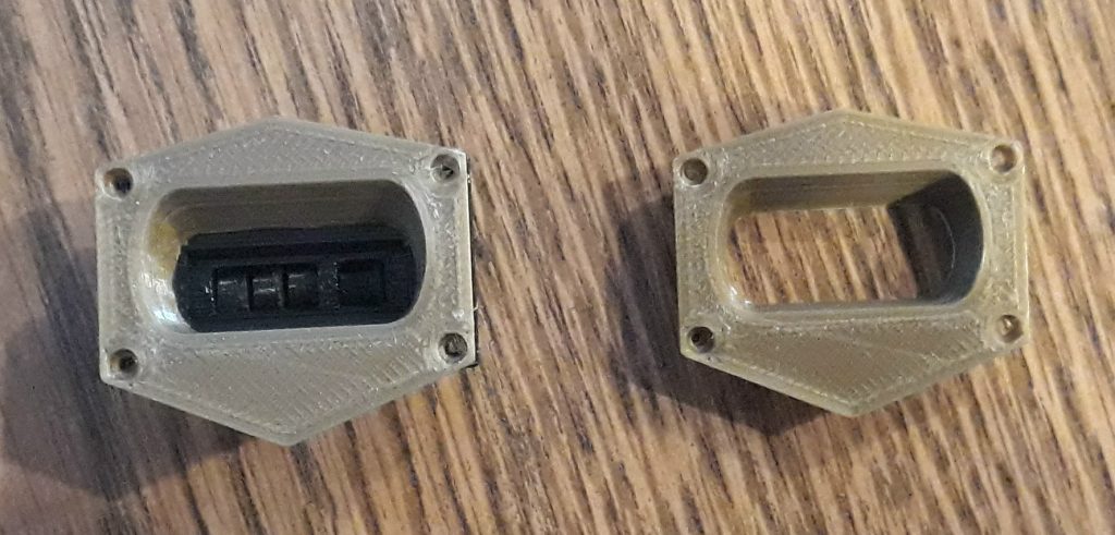
Bezel along on the right, complete test-fit display on the left.
(Photo: The Apollo Education Experience Project)


I made a sextant out of celestron telescope parts, a microwave dish aiming periscope and an illuminated retical for telescopes. With a moving trunion and mirror angle motor I can get trunion angles and offset angles off any star in the sky.
I dont have the software to drive the chinese motors to convert AB pulses to degrees but maybe you do. If you want to do the software I can give you a Sextant and SCT.
Sam